The Flow Tab
About the Flow Tab
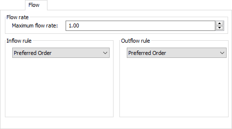
The Flow Tab determines the (initial) flow rates of FloWorks objects in the model and the strategy used to divide inflow and outflow over the various ports.
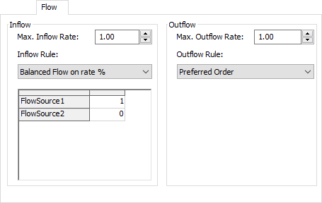
In general the flow tab has two symmetrical panels: one for the inflow side of the object and a similar one for the outflow side. The following properties are available.
Max. flow rate
The maximum flow rate limits the total cumultaive flow rate through all ports. Sometimes you will also see this referred to as the "preferred flow rate", as this is the rate that the object would ideally have, in the absence of up- or downstream constraints.
Inflow Rule / Outflow Rule
If an object has multiple input or output ports, there may be several ways to divide the available flow over these ports. For example, if an object is fed by two unconstraining sources and you set the maximum input flow rate to 10, we could have each source deliver 5 for a total of 10, let one source deliver the full rate of 10 while blocking the other, or anything in between - any flow rate between 0 and 10 (inclusive) is possible for the first source where the second source will deliver the remainder of the maximum flow.
FloWorks provides two strategies to decide how the flow rates should be split in case of multiple input ports. These are called Inflow (or Outflow) Rules and are described below.
Preferred order
The preferred order rule allows you to specify a preferred order for satisfying the maximum possible flow rate, by changing the order in which you connect input or output objects. This rule attempts to always maximize the flow through the first port, then through the second ports, continuing to the last connected port. To change the object that gets the most possible flow while possibly restricting other objects, you may change the order of the connections on the General tab.
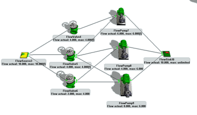
Above, an example is shown of a system with all objects using Preferred Flow for both their input and their output. The flow source has a maximum capacity of 10 that it divides among the flow valves directly connected to it. Since all of these valves have a maximum capacity of 4, the source can provide that maximum to the first two valves, leaving a flow of 2 for the valve connected to the source's last output port.
The valve at the top, FlowValve4, is only connected to one object, FlowPump7. The latter has a maximum capacity of 6 so it gets the full capacity on its first input port. The remaining capacity of 2 can be provided by the second valve, FlowValve5, since FlowPump7 is connected to its first output port and thus has highest priority. The remaining flow of 2 on FlowValve5 goes to FlowPump8 on the second output port, leaving nothing for the final pump FlowPump9.
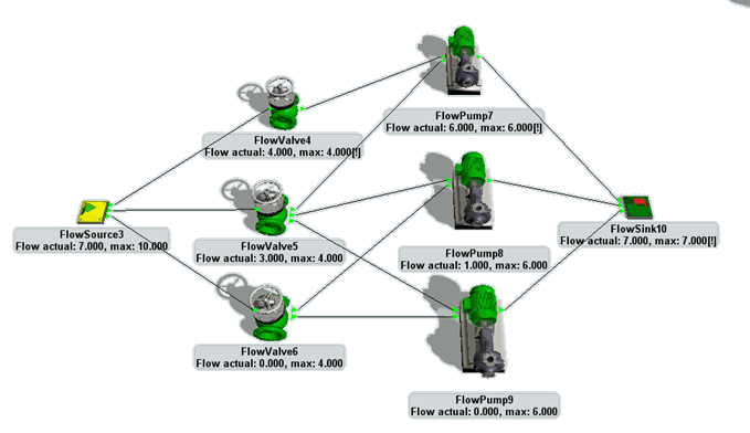
The sink is non-constraining, so all the flow pumps can indeed operate at their maximum capacity. Note that the input rate of the sink is equal to the output rate of the source. If we would set a maximum flow rate on the sink that is lower than the current rate we would see capacities in the system being reduced to match this new constraint, but still giving the highest possible flow through the highest ranked input and output ports whenever possible.
Balanced flow on rate %
This option will always balance the flow between different ports according to the given ratio, while still taking the maximum flow rate into account. When you select the option, a table will be shown with one row for each connected input or output object. You can enter the ratios between the flows to or from this objects in the table. Note that the ratios need not correspond to percentages by adding up to 1 or 100 - in fact FloWorks will normalize the ratios when calculating the maximum flows.
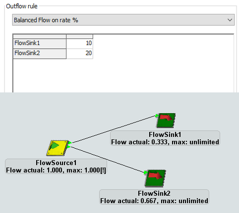
For example, the model was created by connecting a flow source with a maximum output rate of 1 to two unconstraining flow sinks. To ensure that the flow is divided with one third going to the first sink and two thirds going to the second, we set the outflow rule to "Balanced Flow on rate %" with a ratio of 1 to 2. Other values that would have produced the same model would be 10 and 20, 0.3 and 0.6, 33 and 66 or any other two numbers with the same ratio.
The Flow tab adapts to the object
The flow tab may slightly change shape depending on the object whose properties you are editing. For example, the flow pump is not designed for use as a splitter or blender - there are separate objects to do precisely that - so its inflow and outflow rule will be fixed to "Preferred Order".
Also, for content-holding objects the Flow tab will have two symmetrical panels that allow you to set the maximum flow and a flow rule for both the input and the output, as shown in the first screenshot on this page. For objects that cannot hold content, such as the pump, valve and pipe, you can select the inflow rule and outflow rule separately, but only a single field for the maximum flow rate is shown. FloWorks guarantees that the actual input rate and output rate are always equal to each other.
Finally, the source and the sink do not have an input side and an output side, respectively. The Flow tab of these objects will only show the applicable controls.