Mass Flow Conveyor
Overview and Key Concepts
The Mass Flow Conveyor (MFC) is similar to the standard conveyor objects except for a few distinct differences. The biggest difference is that each MFC section (straight or curved) can define how many lanes flow items can move along. If the MFC's output rate is not sufficent to move all of the flow items off of the end of the conveyor, the MFC will back up and all of the lanes will be filled with flow items.
The MFC is a fixed resource. It will continue to receive flow items until its maximum content value is met. Flow items will enter the MFC at the first section and move along the conveyor until it reaches the end of the last section. The MFC will then release the flow item.
Flow Item Drawing and Placement
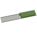
The MFC is designed to handle large numbers of flow items. By default, when a flow item enters the MFC it is no longer drawn in the 3D view. Instead, a representation, or virtual flow item is drawn as a cylinder. This allows for faster drawing and less computations as the flow items move down the MFC. If visual display is important, perhaps when exporting a video of your model, the cylinders can be replaced by the 3D shape of the represented flow item, or by another 3D shape.
The virtual flow items will draw at the size specified in the MFC's properties window, not at the size of the flow item. By default, the bottle diameter and height are equal to that of a regular soda can. The color of these flow items can be set for the entire MFC, or the color can be set for each section. If you are using a 3D shape to draw your flow items with, you can cause the bottle to change its shape at each section by changing the 3D frame index or drawing a completely different 3D shape. This might be done if you want to show the state that the bottle is at as it travels along the MFC. For instance, the bottle may start out as empty, and then as it moves along the conveyor, it is filled with a liquid. Then a cap is put on the top.
Decision Points
Each section can have any number of decision points assigned to it. A decision point can define state change triggers with the following criteria:
- Full State Changed - The trigger fires when the decision point's associated cross line changes from being not full to being full or vice versa. Full is when the content of the cross line (the number of flow items) is equal to the number of lanes.
- Slowed State Changed - The trigger fires when the decision point's associated cross line changes from being not slowed to being slowed or vice versa. Slowed is when some of the bottles in the cross line could not be transferred to the next cross line.
- Stopped State Changed - The trigger fires when the decision point's associated cross line changes from being not stopped to being stopped or vice versa. Stopped is when none of the bottles were able to be moved to the next cross line.
- Empty State Changed - The trigger fires when the decision point's associated cross line changes from being not empty to being empty or vice versa. Empty is when no bottles are in cross line.
States
The MFC doesn't implement any states, however, the individual sections and decision points do have states. You can also use the content graph to get statistics.
Events
The MFC implements the standard set of events that a Fixed Resource implements. In addition, decision points on the MFC have the following events:
- On Empty State Changed
- On Full State Changed
- On Slowed State Changed
- On Stopped State Changed
Each event has the following parameters:
| Parameter | Type | Description |
|---|---|---|
| Into State | int | 1 if the decision point is entering into the state, 0 if it is leaving the state |
See Decision Points above for information on each state change.
Properties
The MFC object has six tabs with various properties. The last four tabs are the standard tabs that are common to all fixed resources. For more information about the properties on those tabs, see:
The remaining two tabs, the Mass Flow Conveyor tab and the Sections tab are unique to the MFC object. The properties on these tabs will be explained in more detail in the next two sections.
The Mass Flow Conveyor Tab
The Mass Flow Conveyor tab has the following properties:
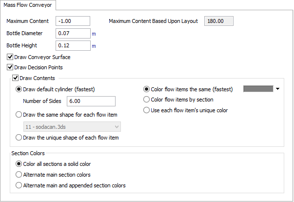
Maximum Content
This number defines how many flow items the MFC will be allowed to hold at a given time. if this number is less than 0, the Maximum Content Based Upon Layout value will be used.
Maximum Content Based Upon Layout
This number is calculated based upon the layout of the MFC. It is equal to each section's calculated length multiplied by the number of lanes for that section divided by the bottle diameter. If the Maximum Content is greater than the Layout's Maximum Content, flow items above the maximum content will not be drawn.
Bottle Diameter
This is the diameter that each bottle, or flow item, while it is on the MFC. The diameter affects the layout of the MFC where each section's width is equal to the bottle diameter multiplied by the number of lanes in that section. This diameter overrides the size of flow items.
Bottle Height
This is the height of each bottle, or flow item, while it is on the MFC. The height is only for visual purposes and does not affect the MFC layout. The height overrides the size of flow items.
Draw Conveyor Surface
If checked, the MFC will draw its surface.
Draw Decision Points
If checked, the MFC will draw decision points.
Draw Contents
If checked, the MFC will draw its contents. Unchecking this box so the MFC will not draw its contents can improve 3D drawing performance.
Draw default cylinder (fastest)
Draws all flow items as cylinders with the defined number of sides. This is the fastest method for drawing the contents of the MFC. You can define how many sides the cylinder has. The more sides, the better the cylinders will look but the slower it is to draw.
Draw the same shape for each flow item
This will draw each flow item using the specified 3D shape. The more complex the shape, the slower it is to draw. If this option is selected, sections will be able to draw the MFC's shape, defined here, or they can draw a different 3D shape. This allows you to show the state of the flow item as it moves through the MFC.
Draw the unique shape of each flow item
This is the slowest drawing method. Each virtual flow item will be drawn using the 3D shape of the flow item. The size of the flow item is defined by the Bottle Diameter and Bottle Height of the MFC. If this option is selected, sections will be able to change the 3D shape's shape frame. This allows you to show the state of the flow item as it moves through the MFC.
Color flow items the same (fastest)
Draws all flow items with the specified color. This is the fastest method for coloring the contents of the MFC.
Color flow items by section
This will color all flow items in a section the same color. Each section can define a different color or use the previous section's color.
Use each flow item's unique color
This is the slowest coloring method. When each virtual flow item is drawn, the color of the original flow item will be copied.
Color all sections a solid color
This uses the MFC's color to draw all section's surface with.
Alternate main section colors
This will alternate each section's surface color to make distinguishing between sections easier.
Alternate main and appended section colors
This will alternate each section and each appended section's surface color.
The Sections Tab
The Sections tab has the following properties:
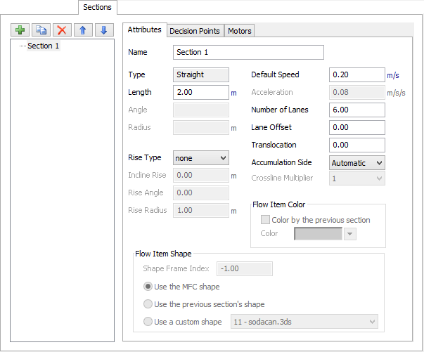
This tab allows you to configure the layout of the MFC, its decision points and attached motors.
Sections List
The sections list on the left side of the tab displays the list of the MFC's sections. You can add and remove sections, duplicate existing sections and reorder sections. Click on a section to display its properties to the right.
When adding a section there are three options. Straight, Curved and Appended Section. Selecting the Appended Section gives you two more options, Straight and Curved. For information on appended sections, see the Using Mass Flow Conveyors page.
| Icon | Description |
|---|---|
 |
This button adds a straight, curved or appended section. |
 |
This button duplicates the currently selected section. |
 |
This button deletes the currently selected section. |
 |
This button reorders the currently selected section up in the list. |
 |
This button reorders the currently selected section down in the list. |
Attributes Tab
This tab displays each section's properties which include layout, behavior and visuals. It has the following options:
- Name - The name of the section.
- Type - This readonly value displays whether the section is straight or curved. The section type cannot be changed once it has been created.
- Length - For straight types this is the horizontal length of the section.
- Angle - For curved types this is the angle of the curve. This can be a positive or negative number.
- Radius - For curved types this is the radius of the curve. A spiral conveyor can be created by setting the radius greater than 360 and using an incline rise.
- Rise Type - Defines the rise type of the section. For a straight section this can be an incline or a wedge. For a curved section this can be an incline.
- Incline Rise - For inline rise types this is the vertical height of the rise.
- Rise Angle - For wedge rise types this is the angle of the wedge. This can be a positive or negative number.
- Rise Radius - For wedge rise types this is the radius of the wedge.
- Default Speed - Defines the starting speed of the section. If the section is connected to a motor this value is ignored. If the selected section is an appended section, the speed will be inherited by the parent section.
- Acceleration - Defines the acceleration of the section. If the selected section is an appended section, the acceleration will be inherited by the parent section.
- Number of Lanes - Defines how many flow items can fit side by side in this section. This value will affect the width of this section based upon the MFC's bottle diameter.
- Lane Offset - The lane offset will shift the start of the section the specified numer of lanes. This value can be positive or negative.
- Translocation - This will shift the end of the section by the specified number of lanes. The start of the section will remain fixed causing the section to be skewed. This value can be positive or negative.
- Accumulation - Select which side of the section the flow items should accumulate on. Automatic will cause the accumulation to be based upon the section's layout. For example, a curved section will accumulate to the outer edge. Automatic will look at the previous section's accumulation if the layout is such that it doesn't affect the accumulation.
- Crossline Multiplier - The crossline multiplier allows you to define more or fewer crosslines in the section. More crosslines means greater accuracy but increases the number of events that are created and slows down the model. Fewer crosslines decreases accuracy but increases the model run time by decreases the number of events.
Flow Item Color Group
If the MFC uses Color flow items by section, the following options will be available:
- Color by the previous section - If checked, flow items in this section will be colored based upon the previous section's flow item color.
- Color - Specifies the color of flow items in this section.
Flow Item Shape Group
If the MFC uses Draw the unique shape of each flow item, the following option will be available:
- Shape Frame Index - If the flow item has define shape frames, this number will specificy which shape frame to draw for this section. If the frame index is 0, the base frame will be drawn. If the frame index is less than 0, the frame index used in the previous section will be used. Shape frames can be defined in the Flow Item Bin.
If the MFC uses Draw the same shape for each flow item, the following options will be available:
- Use the MFC shape - This will use the shape defined by the MFC under Draw the same shape fro each flow item to draw flow items in this section.
- Use the previous section's shape - This will draw flow items in this section using the 3D shape defined by the previous section.
- Use a custom shape - This will draw flow items in this section using the specified 3D shape.
Decision Points Tab
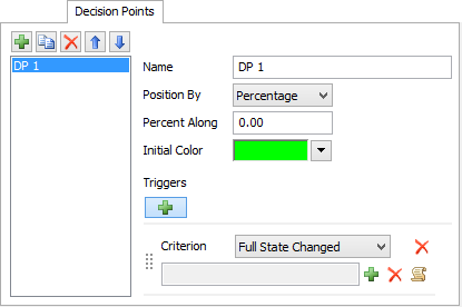
This tab displays the currently selected section's decision points. It has the following options:
- Decision Points List - Displays the section's decision points. You can add, duplicate, remove and reorder decision points.
- Name - The name of the decision point.
- Position By - The decision point can be positioned by distance or percentage.
- Percent/Distance Along - If Distance is selected in the Position By, the Distance Along is in model length units measured from the start of the section. If Percent is selected, the Percent Along is defined as 0 - 100 with 0 being the start of the section and 100 being the end of the section.
- Initial Color - The color of the decision point at reset.
- Triggers - Use the add button to add triggers to the decision point. Each trigger has a Criterion which defines when the trigger is fired, and a code field. Use the predefined pick lists or write custom code to define the behavior of the decision point when the trigger is fired.
Motors Tab
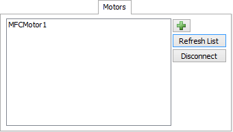
This tab displays the currently selected section's connected motors. It has the following options:
- Motors List - Displays the currently connected motors. Each section can have up to two connected motors.
- - Displays a list of motors that can be
connected to this section. Motors can also be added in the 3D view by holding the A key and click-dragging
from the motor to a section.
- Refresh List - Refreshes the list of connected motors.
- Disconnect - Disconnects the selected motor from the section. Motors can also be removed in the 3D view by holding the Q key and click-dragging from the motor to a section.