Creating Custom Animations
Introduction to Animations
Many of the 3D objects in FlexSim Library come pre-programmed with some basic animations. While those animations are generally enough for most simulations, you can also create your own custom animations for FlexSim objects and your custom 3D objects.
You can use the Animation Creator tool to create these custom animations. Using the Animation Creator you can:
- Import and edit animation files created in other animation software applications. You can import custom objects with bone animation files from third-party software applications such as Blender, Poser, Mixamo, or 3ds Max.
- Export animations created in FlexSim to other FlexSim users. Any animation files you create using the Animation Creator can be easily shared with other FlexSim users if they want to use that animation in a different simulation model.
- Create variables and triggers that can dynamically change how an object is animated during a simulation run or get information from an animation-related object. Using the Animation Creator, you can create variables that change an object's animation under certain conditions during a simulation run. For example, you could create a variable that slows down or speeds up an animation based on certain conditions. You could also use variables to change the position, rotation, or color of an object's animated components under certain conditions.
- Customize how flow items are animated. You can use the animation creator to create surrogate objects. Surrogate objects are objects that can control the way flow items will be animated when they are being handled by a task executer or a fixed resource. For example, you could animate a surrogate object so that it will rotate when it is inside a processor.
Key Terms and Definitions
The following are some important terms you'll need to know in order to use the Animation Creator:
Animations
An animation is a sequence of object movements that are triggered at various points in a simulation run. You can animate any object that is capable of moving throughout the model or interacting with flow items, such as task executers or fixed resources. In FlexSim, animations are made up of: 1) components and 2) keyframes, which are defined in the following sections.
Components
Components are 3D shapes that comprise an object. These shapes can be combined together and be positioned in such a way that looks like movement when an animation is run. The standard FlexSim objects generally come pre-programmed with at least one component, but some might have more. You can also add a custom component to a standard FlexSim object.
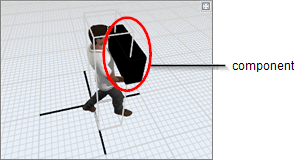
The following image shows a custom component that has been added to the Operator's Walk Loaded animation:
Keyframes
A keyframe is a drawing of an object that defines the starting and ending point of an animation segment. A component keyframe consists of a set of values that define the component's properties such as its position, size, rotation, shape, color, etc. In other words, keyframes are the saved values for different properties of a given set of components.
Usually, you will put two or more keyframes on a timeline to define the beginning and end of an animation segment. Although keyframes typically define the beginning and end of an animation, you should also put keyframes any place that marks a major movement between components. See the example in the following section about tweening for more information.
Tweening
Tweening is when FlexSim automatically creates the animation transitions between two keyframes. FlexSim has the capability to tween two components based on many different factors such as an object's position, rotation, size, color, etc. For example, imagine you want to animate a cube component that will change from blue to red in about 5 seconds, as illustrated in the following image:
The timeline for this kind of animation would look approximately like the following image:
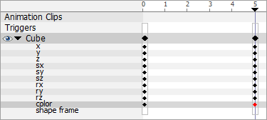
Notice that in this timeline, the cube had a keyframe at time 0. On this keyframe, the cube's color component is set to blue. There is a second keyframe at time 5 where the color is set to red. While the animation is running, FlexSim will automatically tween the colors, which means that it will create all the transitional colors between time 0 and 5. In other words, you don't have to manually create a purple color halfway through the animation because FlexSim will do it for you when it tweens the two keyframes.
As a general rule, you should try to put keyframes in places that mark the begining and end of a major movement. For example, let's say you wanted to animate an operator walking. The first keyframe should be the position the operator starts from (perhaps a standing position) and the next keyframe might be the right leg extended and so forth. FlexSim will then automatically generate a smooth transition between the keyframes to create the illusion of leg movement during a simulation run.
Surrogates
A surrogate is a special kind of component that will be replaced visually by another object (such as a flow item) when an animation is running in the simulation model. It acts like a placeholder for another object in an animation. Whereas components are part of an animation visually (meaning it will show up in animation), a surrogate can be visually replaced by another object.
The most common reason for turning a component into a surrogate is to change the animation of a flow item while it is being handled by one of the fixed resources or task executers during a simulation run. Once a component has been converted to a surrogate in the animation creator, it can be used to change a flow item's position, size, or rotation in an animation while a fixed resource or task executer is handling it. When the fixed resource or task executer begins handling the flow item, the flow item's shape will be replaced by the shape indicated in the Draw Surrogate menu in the surrogate's Quick Properties.
For example, in the following image, you'll see that a surrogate (a cube) has been added to a processor's animation:
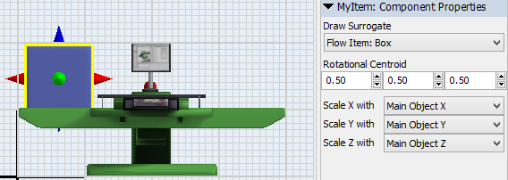
In this example, the cube will be replaced by the flow item box shape when it enters the processor because that is what was selected in the Draw Surrogate menu. If the Draw Surrogate menu instead had been set to None, the flow item will change to the shape of the surrogate object (a cube) when it enters the processor. The flow item will then adopt the same position, size, or rotation coordinates that were used in the surrogate's animation.
Animation Variables
Animation variables can possibly change the way objects are animated based on conditions that might change during a simulation run. For example, a variable on a component keyframe can change a component's position, rotation, size, color, shape, etc. based on dynamic conditions in the simulation model. You could also use a variable to determine how fast a particular animation should run based on certain conditions.
Keep in mind that an animation variable is basically a reference point to an animation-related object, component, or keyframe. Animation variables can point to:
- Components
- Surrogates
- Keyframe times
- Time gaps
- Component keyframes (such as the component's position, size, rotation, color, or shape frame)
Once you've created an animation variable, you can reference that variable in a FlexScript command. (See Animation Commands for more information.) FlexScript commands can either get information about a variable or it can set the value of a variable (thereby possibly changing the variable). For example, if you want to dynamically change the length of your animation based on parameters in your model at run time, you can create an animation variable that points to a time gap, and then set that animation variable through a keyframe trigger or from a trigger in your model.
Keyframe Triggers
Triggers can be added to animations that will fire when the animation gets to a specific point in the animation's timeline. They are added through the timeline. Triggers allow you to dynamically change or update animation variables, stop the animation, change some parameter in your model, or execute any other FlexScript code.
Opening the Animation Creator
To open the animation creator:
- You first need to add the object you want to animate to the 3D simulation model.
- Then, right-click the object and select Edit, then Animations from the menu. The animation creator for this object will open in a separate window (tab) in the center pane.
Alternatively, you can access the animation creator by:
- Double-clicking the object to open its properties window.
- Under the General tab, in the Appearance group, click the Edit button next to the Visuals/Animations property.
Overview of the Animation Creator
This section will provide an overview of the Animation Creator UI. The most important elements of the animation creator are labeled in the following image:
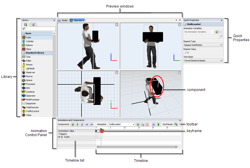
Note that in the preceding image, the toolbar is slightly truncated. See Toolbar for an explanation of the full toolbar accompanied by complete images.
Each element will be described in more detail in the following sections.
Preview Windows
Located in the upper portion of the animation creator, the preview windows allow you to see how your objects will appear visually during the animation. There are four different panes in this window that allow you to see the animation from various angles.
You'll be able to see the object's animation in action when you run an animation using the animation control bar. You can also scrub the timeline (which means to put the cursor at a particular place in the animation timeline) to see how the object will look at specific points in the animation.
If you add any components to the animation, you can also use the preview windows to manually resize, reposition, or rotate the component object. You can also zoom in and out or change the angle the same way you would in the 3D model.
In the top right corner of each preview pane, you can click the Maximize button
 to hide the other 3D windows and expand
the selected 3D window to take up the entire preview window. Click the button a second time
to return to the default view.
to hide the other 3D windows and expand
the selected 3D window to take up the entire preview window. Click the button a second time
to return to the default view.
If you right-click anywhere inside a blank spot of the preview window, a menu will pop up with one option: Flip Axis. This option flips the axis of the view. For example, if you flip the axis that is currently displaying the top view, it will display the bottom view. This option is only available in the side, front, and top 3D views.
Components
Components are 3D shapes that comprise an object. These shapes can be combined together and be positioned in such a way that looks like movement during a simulation run. Any object can possibly have one or more components or you can add a component to a standard FlexSim object.
The following image shows a custom component that has been added to the operator's Walk Loaded animation:
Library
When the animation creator is open, the Library will change to display some basic objects that can be added as components in the animation.
Quick Properties
You can use the settings in Quick Properties to change the basic functionality of the animation, such as its repeat type and time base. You can also use Quick Properties to create new animation variables.
Animation Control Panel
Located in the lower portion of the animation creator, the animation control panel is the primary workspace you'll use while working inside the animation creator, as shown in the following image:
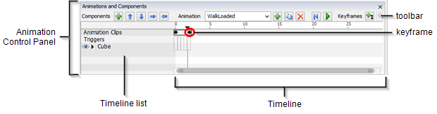
Note that in the preceding image, the toolbar is slightly truncated. See Toolbar for an explanation of the full toolbar accompanied by complete images.
The following sections will explain the different elements of the animation control panel.
Timeline
The timeline is a chronological display of the animation over time. You can also scrub the timeline (which means to put the cursor at a particular place in the animation timeline) to see how the object will look at specific points in the animation.
You can also drag keyframes along the timeline to make them longer. As the space increases between keyframes on the timeline, the tweening animation will take longer.
If you want to zoom in or out of the timeline, you can use either one of the following methods:
- Click the Zoom button
 on the toolbar to zoom in or out on the timeline to make all the keyframes fit on the
screen.
on the toolbar to zoom in or out on the timeline to make all the keyframes fit on the
screen. - Position the mouse above the timeline and press the Ctrl key while scrolling the mouse wheel.
- Click the right end of the scroll bar underneath the timeline and drag it to zoom in and out, as shown in the following image:
Timeline List
The timeline list is kind of like a header for the timeline, showing you each element in the animation in the timeline. The timeline list displays any animation clips, triggers, and/or components that have been added to this object's animation.
If you click on the arrow next to a component, you can expand the list to show the component's individual properties on the timeline, as shown in the following image:
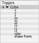
Once the component properties have been expanded, you can add component keyframes to the timeline in order to change the way a particular component property will behave at various points in the animation.
Keyframes
A keyframe is a drawing of an object that defines the starting and ending point of an animation segment. In the user interface, keyframes look like a small black diamond that turns red when it is selected. A component keyframe consists of a set of values that define the component's properties such as its position, size, rotation, shape, color, etc. In other words, keyframes are the saved values for different properties of a given set of components.
You will put keyframes on a timeline to define the beginning and end of an animation segment. Although keyframes typically define the beginning and end of an animation, you should also put keyframes any place that marks a major movement. See Keyframes and Tweening for more information.
Toolbar
The toolbar contains all the tools you'll need to create and edit custom animations:
- Component tools - Used to add or reorder new components.
- Animation tools - Used to select, add, copy, or delete new animations.
- Keyframe and Timeline tools - Used to control playback of the animation preview and to add or edit keyframes on the timeline.
- Base Position tools - Used to save the base position of the components.
Creating and Importing Custom Animations
You can create your own custom 3D objects and animations using third-party software applications such as Blender, Poser, Mixamo, or 3DMax. To import a custom object and animation:
- First you need to create a custom object to act as your basic template. Drag either the Basic FR object or the Basic TE from the Library into your simulation model. (Use the Basic FR object if you want to create a fixed resource or the Basic TE if you want to create a task executer.)
- Click the Basic FR object or the Basic TE object to select it.
- In Quick Properties under General Properties, click the
arrow next to the Shape box
 to open a menu.
 - Select Browse from the menu and navigate to the location of your custom 3D object's file. Select the file that you want to import. The Basic FR object or the Basic TE will be updated to the new shape that you imported.
When you import an object, it will also import any animations that are associated with it. In order to create custom animations, you might need to create animation clips for the object. See the next section about Creating Animation Clips for more information.
Creating Animation Clips
When you create a custom object using third party software, you might typically want to create more than one animation for it. For example, the default Operator object in FlexSim has three different animations: walking, walking while carrying a load, and standing. So, if you wanted to make your own custom Operator object, it should probably have at least these three same animations.
However, some animation software programs only allow you to export all these animations as a single animation file. Consequently, when you import these files into FlexSim, you'll need to cut the animation file into individual clips using the clip editor in the animation creator.
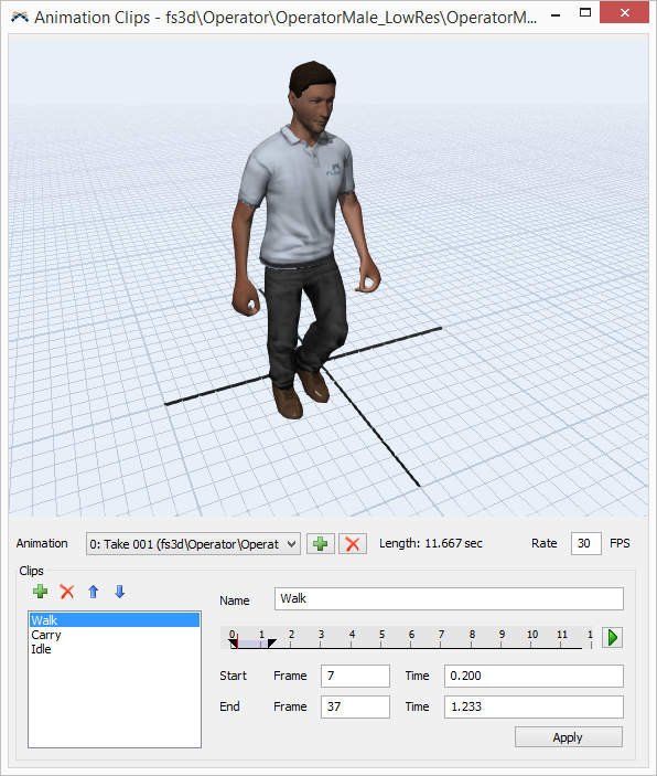
To create animation clips:
- With the animation editor open for the object you want to animated, click the
Bone Animations button
 on the animation toolbar and select Edit
Animation Clips from the menu. This will open the clip editor, as shown in the following
image:
on the animation toolbar and select Edit
Animation Clips from the menu. This will open the clip editor, as shown in the following
image: - In the Clips group, click the Add button
 to add a new clip to the list of clips.
 - Give the clip an appropriate name by typing a new name in the Name box.
- If needed, press the Play button
 to preview the full animation.
 - Now you'll need to choose which section of the animation should be included in this clip. Drag the sliders on the timeline to the beginning and end of the section you want to include in this clip. Alternatively, you could manually set the exact frames and times that should be included using the Frame and Time boxes below the timeline.
- If needed, you can also change the rate of frames per second using the Rate box.
- Click the Apply button to save the changes to the clip.
- Make any other necessary changes and then close the window.
- Now when you click the Animation menu in the animation control panel, the new clip you created will appear in the list of available animations.
You can also add additional animations from other external files using the Add
button beside the Animation dropdown. This
process works correctly if the other animation file has the same skeletal bone structure and
bone names as the imported shape file.
Use the animation creator's timeline if you want to combine one or more clips together.
Animating Bones Directly
You can directly animate a shape with bones using the Bone Animations
button and selecting Animate Bones Directly.
The bones in the shape will be shown in the Animations and Components hierarchy list and displayed in the 3D views. With this option enabled, you can edit the rotations, positions, and sizes of the bones directly using keyframes as you would any other component.
Any keyframe animation of the bones will be applied as an additional transformation after any animation clips are applied, so you can use animation clips, direct bone animations, or a combination of both.
The Reset Bone Positions options will set all of the bones back to their unchanged positions. You may want to use this option to add a keyframe at the beginning and end of any animations that animate the bones directly, especially when combining direct bone animations with animation clips.
Each component's Quick Properties panel has a Parent to Bone option that you can use to animate a component along with a bone when animating bones directly. This can be used for adding additional shapes that animate with the object, such as a hat or a clipboard. The component's position will be relative to the bone instead of the main object when using this option, so you will probably want to set the component's position close to [0, 0, 0] to be near the bone.
Animation Commands
The following commands deal with animations:
startanimation(object, animation) - Starts an animation on the object. Animation can be either a string value that is the name of the animation, or it can be a number which is the animation rank.
stopanimation(object, animation) - Stops an animation on the object. Animation can be either a string value that is the name of the animation, or it can be a number which is the animation rank.
resumeanimation(object, animation) - Resumes an animation on the object that was previously stopped. Animation can be either a string value that is the name of the animation, or it can be a number which is the animation rank.
getanimationvar(object, animation, "varname") - Returns the value of an animation variable.
setanimationvar(object, animation, "varname", value) - Sets the value of an animation variable. Value can be a number or object and is based upon what the animation variable is linked to.