Importing CAD Drawings and Floor Plans
Introduction
Often one of the first steps in building a simulation model is to create or import a floor plan of the facility you want to simulate.
Although importing a floor plan is optional, you might find that a floor plan is useful because:
- Floor plans can act as a guide when placing 3D objects in your simulation model. Floor plans can keep your simulation model anchored in the physical realities of the facility you are trying to model.
- Floor plans ensure model accuracy. The distance between two objects can sometimes affect the quality of the data coming out of your simulation model. For example, it can change how long it takes to transport a flow item or walk from one location to another. Tiny discrepancies in time can add up gradually, causing skewed results. Using floor plans can help reduce some of those inaccuracies.
You can use use more than one floor plan in your 3D model if needed.
The ideal floor plan file is an AutoCAD drawing. These files usually have a .dwg file extension. You could also possibly import an image file (.png, .bmp, .jpg, .gif, or .ico) that has an accurate drawing of your floor plan. However, be aware that these images sometimes don't scale as well as AutoCAD drawings.
FlexSim can't import Revit files (.rvt). However, Revit has an option to export to .fbx, which can be imported in FlexSim.
Preparing Floor Plan Files Before Importing
Before importing an AutoCAD .dwg file, consider making some improvements to your floor plan file, as discussed in the following sections.
Remove All Unnecessary Information
AutoCAD files typically include much information that is unnecessary to the simulation. Typically, all a simulation needs is a basic layout. Removing information that is extraneous to the simulation will make your model more clear and reduce the burden on your graphics card. As a result it will be easier to build and present the model.
Remove any parts of the drawing that are not pertinent to the simulation study. You should especially consider removing any text, but also possibly grids and hashing as well. Also, check to ensure there aren't any accidental elements on the outer fringes of the AutoCAD drawing that could cause problems once it is imported into FlexSim.
Adjust the Scale to FlexSim Units
AutoCAD files are often scaled in inches. FlexSim models are often scaled in feet or meters. You might need to rescale the AutoCAD file so that it will work appropriately in FlexSim. For instance, to convert from an AutoCAD file in inches to a FlexSim model in feet, the scale factor will be 1/12. To determine how much to scale, follow these steps:
- Measure a known distance in AutoCAD ("_dist").
- Apply the following equation: scale factor = FlexSim distance / ACAD distance.
To scale objects in AutoCAD follow these steps:
- Use Ctrl+A to select all the objects in the drawing.
- Type "_scale" in the command prompt or select the scale command from the menus.
- Click the reference point that will move.
- Type # then the location in the calculated scale factor in the command prompt.
Move Objects to the Origin
AutoCAD drawings are often drawn using a specific coordinate system. This usually means that the objects are not located near the origin (0,0,0). When a .dwg file is imported into FlexSim, it is positioned in FlexSim's coordinate system according to the .dwg's positioning. So if the origin point of your AutoCAD file is very far away from the actual drawing, when that .dwg file is imported into FlexSim, the layout will also be very far away from the model's origin position in FlexSim. To avoid experiencing this problem, move your AutoCAD objects to the origin.
To move your AutoCAD objects to the origin:
- Select the objects you want to move.
- Type "_move" in the command prompt or select the move command from the menu.
- Specify a reference point.
- Type in the desired location of that point in the command prompt.
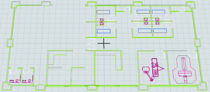
Importing a Floor Plan File
You will use the Model Background tool in the Toolbox to add a floor plan to your model. The Toolbox is where you can manage all the different tools that you are using in your simulation model. To find the Model Background tool:
- Click the Tools button on the main toolbar to open the Toolbox in the left pane.
- Click the Add
 button to open a menu. Point to Visual, then select
Model Background to add a background to the model.
button to open a menu. Point to Visual, then select
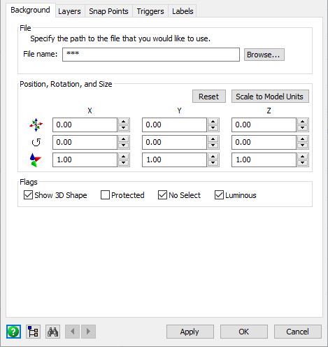
Model Background to add a background to the model. - In the Background tab, click the Browse... button to navigate to the file.
- Navigate to your the file location, select the file and click the Open button.
- You can change the position, size, or rotation of the CAD drawing. If your CAD drawing was created in units different from your model, you can press the Scale to Model Units button to convert the drawing's scale to match your model's units. It will prompt you to select the units the drawing was originally created with. Press the Reset button to reset the background's spatials.
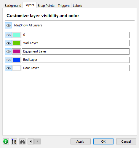
- In the Layers tab, you can change the color of the different layers in the CAD drawing and turn off the visibility of specific layers. You can experiment with other colors as desired.
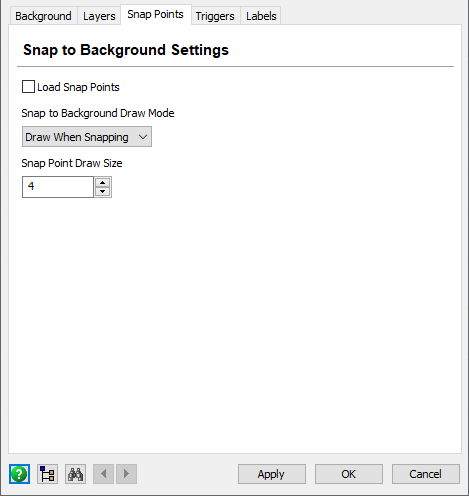
- In the Snap Points tab you can access the drawing's snap points in your FlexSim model. Using these settings, you can enable snap points and then determine whether you want the drawing's snap points to be visible in the model or not. The default option is to draw the snap points whenever you are dragging an object in the 3D model. See Working With Snap Points for more information.
Editing and Deleting Floor Plans
If you need to make changes to the CAD drawing after you're finished, go to the Toolbox and double-click on the Model Background you want to edit to open its Properties window.
If needed, you can also delete the CAD drawing using the Toolbox. See Deleting a Tool Component for more information.
Troubleshooting Floor Plans
Because AutoCAD is a third-party software, sometimes files created by newer versions of AutoCAD do not always function optimally in FlexSim. This section will discuss common problems and their solutions when importing AutoCAD drawings into FlexSim. If these solutions do not solve your problem, please feel free to contact FlexSim Customer Support at any time.
AutoCAD Drawing Isn't Visible
Sometimes when you import an AutoCAD Drawing, you won't see it in your model.
To fix this problem, make sure that:
- In the background's Properties window in the Layers tab,
make sure the Visibility buttons
 are set to show each layer in your
drawing. You could also try changing the color of the layers to see if that helps
improve their visibility.
are set to show each layer in your
drawing. You could also try changing the color of the layers to see if that helps
improve their visibility. - In the background's Properties window in the Background tab, make sure the Luminous box is checked. (It is checked by default.)
Another problem might be that the point of origin for your AutoCAD file is far away from the actual drawing of your facility for various reasons. To find your drawing, you might need to zoom out of the model until you can see where the drawing is.
AutoCAD Files With References to Other Files Aren't Appearing
Some AutoCAD files contain references to other AutoCAD drawings. For example, a portion of one AutoCAD drawing might include portions of another AutoCAD drawing, which means that the original file is referencing that other drawing. Sometimes when you import one of these drawings into FlexSim, it appears that part of the drawing is missing because it no longer references the other file.
To fix this, you need to ensure that all the referenced files are contained in the same root folder as the AutoCAD drawing that references them.
Strange Location Coordinates
When you import an AutoCAD drawing into your simulation model, FlexSim does its best to find the actual drawing of your facility. However, FlexSim might place the drawing of your facility in strange places in the simulation model (as opposed to setting the location coordinates to 0, 0, 0). This problem is usually caused when the point of origin for your AutoCAD file is far away from the actual drawing of your facility. If desired, you can try to change the location of your drawing by moving it by yourself. You can make these changes in the Background tab of the background's Properties window.
Working With Snap Points
FlexSim uses the term snap points to refer to vertices, lines, arcs and other elements in a AutoCAD drawing. However, it will only use the vertices when snapping it to the background. Typically only advanced FlexSim users need to load the drawing's snap points into their 3D models. You can load the CAD drawing's points into FlexSim's tree nodes to get more control over the way you get information from the drawing in the model. Some people use this functionality to auto-build their models or to get specific data from their models. You can also use snap points to position the objects in the model with more precision. Objects will only snap to the snap points of the first background in the model.
Loading Snap Points
You can load snap points by checking the Load Snap Points checkbox in the Snap Points tab of the background's Properties window. If you do so, consider selecting Always Draw as the Snap to Background Draw mode. Also consider increasing the Snap Point Draw size.
You should also change the model's view settings so that they snap to the background:
- Click a blank area in the 3D model to ensure nothing is currently selected.
- In Quick Properties under the View Settings group, check the Snap to Background checkbox.