Task 1.1 - Tasks Using Standard 3D Logic
Task Overview
In this series of tutorials, you'll learn about the different methods for creating task logic for task executers. If you are unfamiliar with what tasks or task executers are, consider reading Key Concepts About Task Logic before completing this tutorial.
In this first tutorial task, you'll learn how to build tasks using the standard logic that is available on 3D objects. Many of the 3D fixed resources have properties and basic logic that can be used to assign simple tasks to task executers, such as basic loading and unloading tasks or requiring an operator to be present during processing time. This tutorial will teach you how to create the logic for these simple tasks. This task will also include an analysis of the advantages and disadvantages of this method.
When you're finished, your 3D model will work similar to the following image:
Step 1 Build the 3D Model
In this step, you'll build a basic 3D model for this tutorial. You'll first add a plane that will act as a container for the 3D objects in the model. Then, you'll add the 3D objects you'll need for this model.
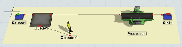
When you're finished, your model should look similar to the following image:
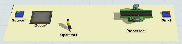
To build this model:
- Make sure your 3D model window is open and active. From the Library, drag a Plane (under Visual) into the 3D model.
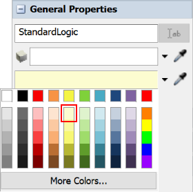
- With the plane selected, in Quick Properties, change the name of the plane to StandardLogic.
- Click the arrow next to the color box to open the color selector menu. Choose the lightest shade of yellow.
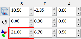
- Change the plane's X-size
 to
to 21.00. - Drag the following 3D objects onto the plane:
- A Source
- A Queue
- A Processor
- A Sink
- An Operator
- Arrange the 3D objects so that they are roughly in the same position as shown in the image at the beginning of this step.
- Double-check that the names of each 3D object ends in a 1, such as Sink1, Queue1, etc.
Check your model to ensure it looks similar to the image shown at the beginning of this step.
Step 2 Create a Task Using Standard 3D Object Logic
In this step, you'll learn how to create simple transportation tasks using the standard logic available on 3D objects. You'll set up the operator to transport flow items from the queue to the processor, which is a relatively easy and straightforward process in FlexSim. You'll also change the item arrival rates and processing times.
To make these changes:
- Create port-connections (A-connects) between the following objects:
- From Source1 to Queue1
- From Queue1 to Processor1
- From Processor1 to Sink1
- Create a center port connection (S-connect) from Queue1 to Operator1.
- Double-click Queue1 to open its properties window.
- On the Flow tab, check the Use Transport box.
- Confirm that the Use Transport box states
current.centerObjects[1]. - Click the OK button to save the changes and close the window.
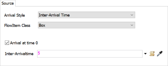
- Double-click Source1 to open its properties window.
- On the Source tab, check the Arrival at Time 0 box.
- In the Inter-Arrivaltime box, delete the current text
and type
5. - Click the OK button to save the changes and close the window.
Reset and run the model:
When a flow item arrives in the queue, the operator will transport it to the processor as soon as the processor is available.
Step 3 Add Additional Operators
Now that you've built a simple transportation task using the standard logic, you'll make it a little more complex by adding a second operator to the model. In standard logic, you need a dispatcher object in order to assign tasks to more than one operator. This step will walk you through the process of setting up this system. When you're finished, your 3D model should look similar to the following image:
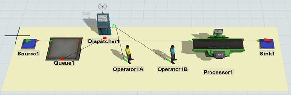
To add a second operator to your model:
- Remove the center port connection between Queue1 and Operator1. To remove center port connections, press and hold the W key while clicking two connected objects.)
- From the Library, drag a Dispatcher and place it on the plane near Queue1.
- Also drag a second Operator onto the plane.
- Rename the operators as follows:
- Click Operator1B to select it. In Quick Properties, click the arrow next to the color selector box and select the turquoise color.
- Create a center port connection (S-connect) from Dispatcher1 to Queue1.
- Create port connections (A-connects) from Dispatcher1 to Operator1A and Operator1B.
- Double-click Dispatcher1 to open its properties window.
- In the Dispatcher tab, click the arrow next to the Pass To box to open a menu. Select Round Robin If Available.
| Object | New Name |
|---|---|
| Operator1 | Operator1A |
| Operator2 | Operator1B |

Reset and run the model:
Notice that not much changes when you add a second operator in this scenario. The system isn't any more efficient than it was with one operator. A lot of that has to do with how the standard logic has operators wait at the processor until it has finished processing a flow item. With this logic, it doesn't help to have an extra operator very much.
Step 4 Add a Second Processor
Transportation tasks sometimes become more complicated when you add more than one possible destination. In this step, you'll add a second processor to the model to see how this affects the standard logic. You'll also add a new type of task for the operator to work on to get a better sense of how adding a second processor affects the overall logic of the system. In this step, you'll require the operator to be present at Processor1A during the processor's setup time. This means that a flow item will sit at the processor until an operator can be present at the processor. The operator is needed to complete the necessary setup before the item can be processed.
To add a second processor and create the setup time logic:
- Remove the port connection from Dispatcher1 to Operator1B. (To remove port connections, press and hold the Q key while clicking two connected objects.)
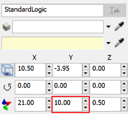
- Click the StandardLogic plane to select it. In Quick
Properties, change the plane's Y-size
to
10.00to make it wider. - Drag a second Processor onto the plane.
- Rename the processors as follows:
- Create port connections (A-connects):
- From Queue1 to Processor1B
- From Processor1B to Sink1
- Create center-port connections (S-connects) from Dispatcher1 to both processors.
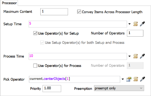
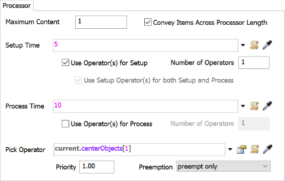
- Double-click Processor1A to open its properties window.
- On the Processor tab in the Setup
Time box, delete the current number and type
5. - Check the Use Operator(s) for Setup checkbox.
- Confirm that the Pick Operator box states
current.centerObjects[1]. - Click the OK button to save the changes and close the window.
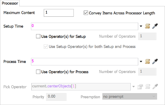
- Double-click Processor1B to open its properties window.
- On the Processor tab, change the
Process Time to
5. - Click the OK button to save the changes and close the window.
| Object | New Name |
|---|---|
| Processor1 | Processor1A |
| Processor2 | Processor1B |
Reset and run the model:
Notice that Operator1A tends to perform tasks in this repeated order:
- Transports items to Processor1A
- Transports items to Processor1B
- Completes the setup time for Processor1A (which takes 5 seconds)
It would probably make more sense if the operator stayed and completed the setup for Processor1A before moving on to transport items to Processor1B. However, the operator doesn't perform the tasks in this order because it determines which tasks it will work on using FIFO logic (first in first out). In other words, the operator will do tasks in the order in which it receives the tasks that are assigned to it.
In this case, Queue1 and Processor1A are both assigning tasks to the operator. Queue1 assigns transportation tasks any time a port is free to receive a flow item. Processor 1A assigns a tasks when it has a flow item and is ready to have the operator assist with the setup time. Because Processor 1A will always assign tasks after Queue1 assigns transportation tasks, the setup time will never be done immediately after Processor1A receives a flow item.
The solution to this problem is to add priority levels and preemption logic to tasks, which will be covered in the next step.
Step 5 Add Priority and Preemption
As you saw at the end of the last step, the operator sometimes performs tasks in a strange order. Because the operator uses FIFO logic (first in, first out) to perform tasks, it sometimes performs tasks in an order that aren't efficient or intuitive. In this step, you'll learn how to fix this problem using task priority levels.
You can override the FIFO task logic by assigning tasks a priority number. Task executers will complete tasks with higher priority numbers before tasks with lower priority numbers. By default, all tasks have a priority level of 0, so task executers will work on any task with a priority of 1 or higher first. (See Task Priorities and Preemption for more information.)
In this step, you'll assign the setup time task a priority of 1 so that the operator will work on it immediately after delivering a flow item to it.
To add priorities to the setup time task:
- Double-click Processor1A to open its properties window.
- On the Processor tab, click in the
Priority box and change the number to
1.00. - Confirm that the Preemption menu is currently set to preempt only.
Reset and run the model:
Notice that the operator now stays and completes the setup time on Processor1A before leaving to work on any other tasks.
Conclusion
Now that you've built transportation tasks using the standard 3D operating logic, you can see that it has a few advantages:
- Quick to set up - You'll notice that setting up a basic model that uses the standard operating logic was relatively fast and easy.
- Ease of use - If you want to create a simple transportation task that uses standard logic, it's probably best to use the standard operating logic because it is so straightforward and simple.
- Preemption and priorities - It's relatively easy to assign priority levels and preemption to tasks using the standard 3D object logic.
However, there are some significant disadvantages that come from using the standard operating logic. To use the example from the model you just built:
- Some inefficiencies - As was pointed out earlier, it's difficult to study how adding additional operators would help make the system efficient or not since they don't always behave how you would expect actual operators to work in a normal business system.
- Unexpected behavior - Sometimes an operator might perform tasks in a strange order because it was responding to the timing of events in the simulation model. Each 3D object has a specific order of events that will control when it does a specific action. One problem is that these order of events aren't easy to discover and their logic isn't visible, so it's difficult to know how to predict or troubleshoot a particular problem caused by timing issues.
- Intermediate tasks - What if you needed to add an intermediate task in between the queue and the processor? For example, imagine that the operator was supposed to stop at a computer and scan the flow item's bar code or that the operator needed to weigh the flow item before putting it on the processor. Custom logic would be quite difficult to build into the standard logic system.
- Model scalability - What if a single flow item needed to be transported by two operators at a time? What if you wanted to be able to add additional operators to study how many employees are needed to keep up with the work load? As soon as you add more complexity to your model, the standard logic becomes a little more difficult to scale.
While it was easy to set up the standard 3D logic for this basic transportation task, it becomes a lot less easy to set up as soon as you try to adapt it or customize it for a more complex business process. That's when it becomes more useful to use the Process Flow tool.
In the next several tutorial tasks, you'll learn about several different methods for creating a simple transportation task using the Process Flow tool. You'll learn more about the advantages and disadvantages of each system. Continue on to Tutorial Task 1.2 - Tasks Using Process Flow.