Working With AGV Paths
Introduction to AGV Paths
AGV paths are the actual paths that AGVs will travel on as they move from one location to another. For that reason, adding a set of paths is generally the first step in building an AGV network.
For the most part, AGV paths can be added, moved, resized, etc. using the same methods you would use for other 3D objects. (See the chapter on Using 3D Objects for more information.) However, the key difference is that AGV paths have two ends: respectively called the start and the end.
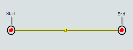
The start is where AGVs enter the path and the end is where AGVs leave the path. Although these two ends are connected, you can move them independently. Curved paths also have a radius, start angle, and sweep angle that you can use to control the arc of the path.
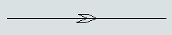
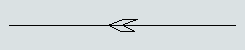
Another key difference is that you can set the direction that AGVs will travel on the paths. Each path has a directional arrow that indicates which direction AGVs can travel along that path:
You can also set a path to allow two-way travel, in which case the directional arrow will look like a hexagon:
Adding Paths
To add a new path:
- In the Library, click the Expand button
 next to the
AGV group to view the AGV objects.
next to the
AGV group to view the AGV objects. - Click the Straight Path or Curved Path object to enter path building mode. When you are in path building mode, your mouse pointer will change to a plus sign with either a Straight Path or Curved Path icon next to it, as shown in the following image:
- Once in building mode, find the position in your 3D model where you want to place the start of the AGV path. When you click on that position in the model and start moving the mouse pointer in a different direction, you'll notice that it begins creating an AGV path. Reposition the mouse pointer until the path's end is at the approximate length and angle you want it to be relative to the start. Click the mouse again to finish building the path.
- After building your first path, you will still be in path building mode. You can add any additional paths as needed. Be aware that the paths will not be connected at this point in the path building process.
- Press the Esc key to exit path building mode.


Joining Paths
One way that you can join paths together is to bring the ends of two paths close enough to the point that they snap together.
Another method is to use the Join Paths object in the FlexSim library. Even though the Join Paths object is in the library, it actually functions more like a tool than a 3D object. When using the Join Paths tool, you can either join the ends of two paths or create junctions coming off one path to another.
To join two paths:
- In the Library under the AGV group, click the Join Paths object to enter path joining mode. When you are in path joining mode, your mouse pointer will change to a plus sign with a Join Paths icon next to it, as shown in the following image:
- While you are in joining mode, hover your mouse over the end of one of the paths until it turns yellow, as though it were highlighted. Click the path and start moving the mouse pointer to the path you want to join. Click the path when it turns yellow as though it were highlighted. The paths should now be joined.
- Check that the direction of the connecting path matches the directions of the joining paths and change the direction if needed. See Changing Path Directions for more information.
- Press the Esc key to exit path joining mode.

Moving or Resizing Paths
Like other 3D objects, AGV paths can be moved or resized using either the Quick Properties pane or your mouse. (See Moving, Rotating, Resizing 3D Objects for more information.)
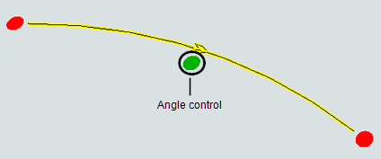
However, the key way in which paths are different is that they have resizing handles at the start and end of the path. Curved paths have an additional green resizing handle that can be used to change the length of curved paths.
The following sections will explain the differences for using either a mouse or Quick Properties to move or resize paths.
Using the Mouse to Move or Resize a Path
In order to use your mouse to move or resize a path, you must first click once on the path to highlight it. After you've taken that step, use the steps listed in following table:
| Task | Process | Demonstration |
|---|---|---|
| To move the entire path | Click anywhere on the path (except the endpoints or other handles) and drag the path to the desired position. |  |
| To move either the start or end of the path | Click the resizing handle on either the start or end of the path. Drag the start or end to the desired position. |  |
| To change the height (Z-axis) of the entire path | Click anywhere on the path (except on the resizing handles) and scroll the mouse wheel up or down until the path is at its desired height. |  |
| To change the height (Z-axis) of either the start or end of the path | Click the resizing handle on either the start or end of the path. Scroll the mouse wheel up or down until the start or end is at its desired height. |  |
| To change the length of the path | Click the resizing arrow on either the start or end of the path. Drag the start or end to the desired length. |  |
Using Quick Properties to Move or Resize a Path
You might want the location, rotation, and size of the path to be more precise in your model. In that case, it's generally a good practice to use your mouse to move or resize your path until it is in the approximate position or size you want it to be. Then you can use the Quick Properties pane to make it more precise.
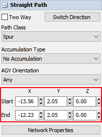
When you highlight a path by clicking it, the right pane displays the Quick Properties for that specific path. The controls that appear in Quick Properties will vary depending on whether you clicked a straight or curved path. Straight paths have settings that adjust the position and size of the start and end of the path, as illustrated in the following image:
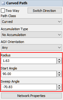
However, curved paths have boxes that adjust the radius, start angle, and sweep angle. The following image shows the Quick Properties for a curved path:
Try experimenting with some of the Quick Properties to get your path exactly the way it should be.
Changing the Radius and Angle of Curved Paths
Curved paths have three additional properties:
- Radius - The radius of the path relative to the midpoint of the hypothetical circle around which the path is drawn. Changing the radius will affect the length of the path because it makes this hypothetical circle larger.
- Start Angle - The angle of the start end of the path relative to the simulation model grid. For example, if the start angle is set to 90, the edge of the path's start direction will be perpendicular to the x-axis of the model.
- Sweep Angle - The angle of the end of the path relative to the start angle. For example, if the start angle is set to 45 and the sweep angle is set to 90, the edge of the path's end direction will be 135 degrees offset from the x-axis of the model.
You can use either the mouse or Quick Properties to change the radius, start angle, and sweep angle of curved paths. It's generally a good practice to use your mouse to move or resize your path until it is in the approximate position or size you want it to be. Then you can use the Quick Properties pane to make it more precise.
To change the radius, start angle, or sweep angle of a curved path, you must first click the path once to highlight it. After you've taken that step, use the steps listed in following table:
| Task | Process | Demonstration |
|---|---|---|
| To change the radius | Click the green resizing handle in the middle of the curved path and drag the mouse to the desired radius. |  |
| To change the start angle | Click the red resizing handle on the start end of the curved path and drag the mouse until the edge of the start is at the desired angle. |  |
| To change the sweep angle | Click the red resizing handle on the end of the curved path and drag the mouse until the edge of the end is at the desired angle. |  |
Changing Path Directions
Every AGV path has a large arrow on it that indicates which direction AGVs will travel on the path:
To change the direction that AGVs travel on a path:
- Click the path to highlight it.
- In the Quick Properties pane, click the Switch Direction button. The direction indicator on the path will now point in the opposite direction.
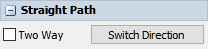
You can also make a path a two way path so that AGVs can travel in either direction on the path:
- Click the path to highlight it.
- In the Quick Properties pane, check the Two Way check box. The direction indicator on the path will now display a hexagon.
Copying Paths
AGV paths can be copied and pasted using many of the same methods you would use to copy and paste other 3D objects. See Copying and Pasting 3D Objects and Properties for more information.