Task 1.2 - Tasks Using Process Flow
Task Overview
In this tutorial task, you'll get a comprehensive introduction to building tasks using task sequences in a process flow. This tutorial will show you some of the advantages and disadvantages of working in Process Flow, such as:
- Adding intermediate tasks
- Combining process flow logic with standard logic
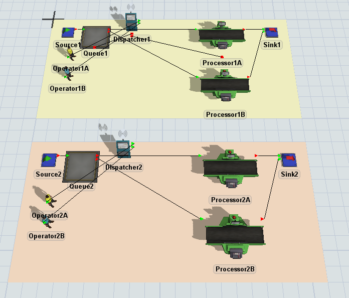
You'll build a series of different simulation models, finally ending in one that works similar to the following image:
Step 1 Copy and Modify the 3D Model
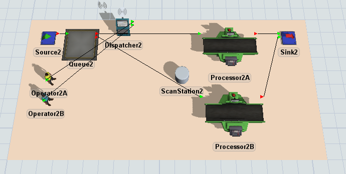
In this step, you'll copy the original system you used to build the standard logic. In the next step, you'll change this system so that it uses process flow logic instead. When you're finished, your 3D model should look similar to the following image:
To copy the plane:
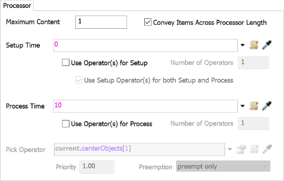
- Double-click Processor1A to open its properties window.
- On the Processor tab, change the
Setup Time to
0. - Clear the Use Operator(s) for Setup checkbox.
- Click the OK button to save the changes and close the window.
- Click the StandardLogic plane to select it.
- Press Ctrl+C to copy the plane and all the objects on it. Click somewhere blank in the model to de-select the original plane. Then, press Ctrl+V to copy the plane.
- With the copied plane selected, change the name of the plane to BasicProcessFlowLogic in Quick Properties.
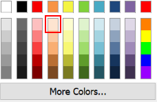
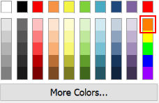
- Click the arrow next to the color box to open the color selector menu. Choose the lightest shade of orange.
- Rename each of the 3D objects on the copied plane replacing any 1 numbers with a 2, such as Sink2, Operator2A, Processor2A, etc.
- Remove the center port connection from the dispatcher to the Queue, and from the dispatcher to Processor2B. (Press and hold the ‘W’ key while clicking and dragging between the two objects.)
Check to ensure that your 3D model looks similar to the image shown at the beginning of this step.
Step 2 Create Tasks Using Process Flow
In this step, you'll add activities to a general process flow to build a process flow that uses task sequence activities to create transportation task logic.
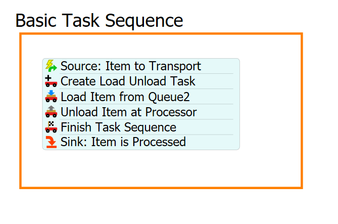
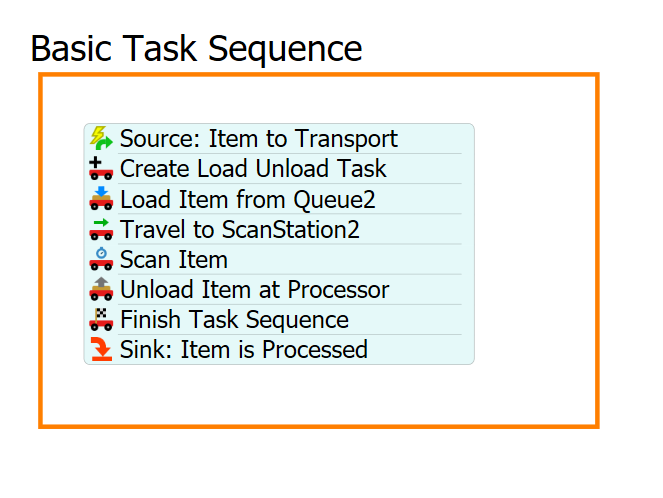
When you're finished, your process flow should look similar to the following image:
For now, you'll merely add and connect these activities to the process flow. You'll edit the properties to add the functionality in a later step.
To add and connect these activities:
- On the main toolbar, click the Process Flow button to open a menu. Select Add a General Process Flow.
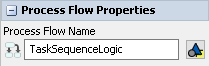
- Click a blank space in the process flow so that nothing is selected. In Quick Properties, change the name of the process flow to TaskSequenceLogic.
- With the process flow open and active, add a Process shape (under Flowchart) from the Library, dragging it into the process flow.
- In Quick Properties, change the name of the shape to Basic Task Sequence.
- Click the arrow next to the Color box to change it to orange. You'll use orange because it matches the color of the BasicProcessFlowLogic plane.
- In the Basic Task Sequence shape, add the following
activities to create a stacked block:
- An Event-Triggered Source (under Token Creation)
- A Create Task Sequence (under Task Sequences)
- A Load (under Task Sequences)
- An Unload (under Task Sequences)
- A Finish Task Sequence (under Task Sequences)
- A Sink (under Basic)
- Rename the activities as follows:
| Activity | New Name |
|---|---|
| Source | Source: Item to Transport |
| Create Task Sequence | Create Load Unload Task |
| Load | Load Item from Queue2 |
| Unload | Unload Item at Processor |
| Sink | Sink: Item is Processed |
Check to make sure your process flow looks similar to the image shown in the beginning of this step.
Step 3 Create the Process Flow Logic
In this step, you'll edit the properties for the activities in the process flow. The following is an overview of how each activity will function:
| Activity | Explanation |
|---|---|
| Source: Item to Transport | The Event-Triggered Source is an event-listening activity that will listen to events in the 3D model. Whenever an item in Queue2 tries to find a Transport, this activity will create a token and release it to the next downstream activity. You'll assign a label to this token named FlowItem that will contain a reference to the specific flow item that triggered the event, as well as a label named Processor which will be a reference to the Processor the Item is going to. |
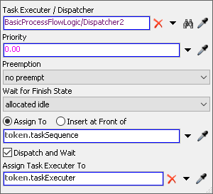
| Create Load Unload Task | This activity will create a new Task Sequence, defining the next several Task Activities into a singular sequence to be executed. It will set a label named taskSequence onto the token to designate the tasks assigned to the sequence. It will send the Task Sequence to the Dispatcher to then assign those series of Tasks to one of the operators. |
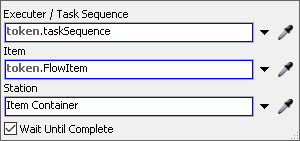
| Load Item at Queue2 | This activity tells the operator which flow item needs to be picked up and where it is located. It will use the taskSequence label to designate that this task is part of the Task Sequence that was created previously. It will use the FlowItem label to designate what is being loaded onto the Transport. |
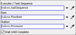
| Unload Item at Processor | This activity tells the operator where to unload the flow item. It will use the taskSequence label to designate that this task is part of the Task Sequence that was created previously and it will use the FlowItem label to tell the operator |
| Finish Task Sequence | Once all the task activities are finished, this activity will designate the Task Sequence as being finished, allowing the operators to be assigned other tasks. |
| Sink: Item is Processed | This activity removes the token from the process flow. You'll use its default settings. |
To create this functionality:
- In the 3D model, double click on Queue2 to open its properties window. Click on the Flow tab, and make sure the Use Transport box is checked. Next to the check box, in the Use Transport field, click on the black arrow to bring up the picklist options. Select the No Transport Reference option. (We will be assigning the task to a Transport in Process Flow.) It should look like this:
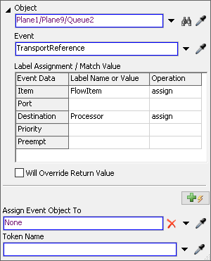
- Click the Source: Item to Transport activity to select
it. Click the Exclamation Point button
 next to this activity to enter
sampling mode.
next to this activity to enter
sampling mode. - In the 3D model, click Queue2 to open a menu. Select Queue2: Transport Reference. The name of the sampled object will appear next to the activity.
- In Quick Properties, in the Label Assignment table, click the cell that is on the Item row under the Label Name or Value column. Type FlowItem. Click on the cell in the same column on the Destination row, and type Processor.
- Click the cell on the Item row under the Operation to open a menu. Select assign. Do the same for the Destination row.
- Click the Create Load Unload Task activity to select it.
In Quick Properties, next to the Task Executer / Dispatcher box,
click the Sampler button
 to enter sampling mode.
 - In the 3D model, click Dispatcher2 to open a menu. Select BasicProcessFlowLogic/Dispatcher2. Leave the rest of the options in the Create Load Unload Task activity as their defaults.
- Click the Load Item from Queue2 activity to select it. In Quick Properties, make sure the Executer / Task Sequence field reads: token.taskSequence.
- Click the arrow next to the Item box to open a menu. Point to Token Label and select FlowItem.
- Click the Unload Item at Processor activity to select it. In Quick Properties, make sure the Executer / Task Sequence field reads: token.taskSequence.
- In the Item box type token.FlowItem.
- In the Station box type token.Processor.
![]()
Reset and run the model:
Similar to the way the operator works with the standard 3D object logic, the operator using the process flow will transport arriving flow items to the processor. You'll also notice that tokens in the process flow represent the flow items as they move through the transportation tasks.
Step 4 Add a Custom Task
Up to this point, you've learned how to merely replicate standard logic using process flow. In this step, you'll begin to see how the process flow method has a major advantage over the standard logic: it can handle customization much better. You can easily create custom tasks that better represent the business system you're trying to model.
In this step, you'll customize the task sequence by adding an intermediate task. You'll add a shape (a kind of visual object) to the 3D model to represent the station where the operator will need to scan flow items before unloading them at the processor:
Then you'll add and rename two additional activities to the process flow that will simulate the scanning tasks. When you're finished, your process flow will look similar to the following image:
The following is an overview of how the two new activities will function:
| Activity | Explanation |
|---|---|
| Travel to ScanStation2 | This activity will tell the operator to travel to the ScanStation2 object. |
| Delay: Scan Item | This activity will simulate the amount of time that it takes to scan the flow item in the computer. You'll set the delay to 1 second. |
To make these changes to your simulation model:
- With the 3D model active, drag a Shape (under Visual) and place it near Processor2A and Processor2B.
- Double-click the Shape to open its properties window.
- In the name box at the top of the window, change the name of the shape to ScanStation2.
- On the General tab in the Flags group, check the Show Name box.
- Press OK to save the changes and close the window.
- In the Basic Task Sequence shape in the process flow, click the stacked block of activities to select it.
- Click the Unlink buttons
 before and after the
Load Item from Queue2 activity to separate it from the
stacked block.
before and after the
Load Item from Queue2 activity to separate it from the
stacked block. - Drag a Travel activity (under Task Sequences) from the Library and insert it after the Load Item from Queue2 activity.
- Drag a Delay activity (under Task Sequences) and insert it after the Travel activity.
- Rename the two new activities:
- Click the Travel to ScanStation2 activity to select it. In Quick Properties, check to make sure the Executer / Task Sequence box reads: token.taskSequence.
- Next to the Destination box, click the
Sampler button
to enter sampling mode.
- In the 3D model, click ScanStation2 to open a menu. Select BasicProcessFlowLogic/ScanStation2.
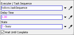
- 15. Click the Delay activity to select it. In Quick
Properties in the Delay Time box, delete the current text
and type
1.00. Make sure the Executer / Task Sequence box reads token.taskSequence. Leave the State box as 3- busy, which should be the default.
| Activity | New Name |
|---|---|
| Travel | Travel to ScanStation2 |
| Delay | Delay: Scan Item |
Reset and run the model:
As you watch, the operators will take the flow item to the scanner and delay briefly before loading it on the processors. Notice that it was relatively easy to insert a simple intermediate task into this process flow. Unfortunately, there is no easy way to create this in the standard logic without writing custom code in Flexscript.
Conclusion
Now that you've built transportation tasks in process flow, you can see that it has a few advantages:
- Ease of use - Like the standard logic, setting up a process flow isn't too difficult, but does involve some more steps. It's also fairly intuitive.
- The logic is more visible - Building the logic in a process flow helps you to see exactly how the operator will perform the tasks. The flowchart-like visuals of the Process Flow tool are a little more intuitive, which makes it easier to troubleshoot and design custom tasks.
- Ability to customize - Unlike the standard logic, it's relatively easy to make custom tasks with a process flow. Notice that in this tutorial, it was relatively simple to insert an intermediate task in between the transportation tasks. While it's certainly possible to add intermediate, custom tasks using just the standard 3D logic, you would have to learn how to write FlexScript code to do so.
By now you hopefully have gotten a good, in-depth introduction to the advantages and disadvantages of building tasks in a process flow. The next tutorial will cover how to build task logic using lists. Continue on to Tutorial Task 1.3 - Tasks Using Lists.