Using Mass Flow Conveyors
Introduction to Mass Flow Conveyor
This topic will explain how the Mass Flow Conveyor works and how to use it in your models. The Mass Flow Conveyor (MFC) is similar to the standard conveyor objects except for a few distinct differences. The biggest difference is that each MFC section (straight or curved) can define how many lanes flow items can move along. If the MFC's output rate is not sufficent to move all of the flow items off of the end of the conveyor, the MFC will back up and all of the lanes will be filled with flow items.
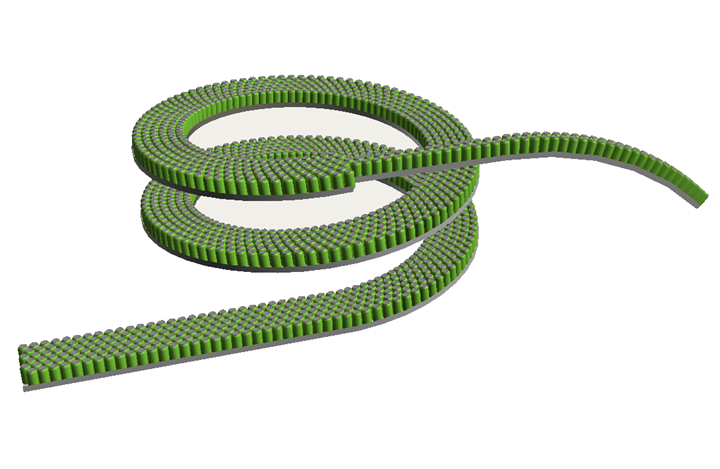
Common uses of the MFC would be for bottling lines.
Visualization
The MFC uses its own drawing logic for displaying its contents. When flow items enter the MFC they are hidden and a virtual flow item is drawn. This virtual flow item may have a completely different 3D shape from the original flow item. The size of the virtual flow item is defined by the MFC and all flow items are drawn at the same size. Once a flow item exists the MFC, it will be at its original size and original 3D shape. The MFC does not modify the flow items.
Since the MFC draws it own contents, it greatly improves the drawing speed of the object. The MFC is designed to handle large numbers of flow items. There are several drawing options for how flow items should look as they move along the MFC. The fastest method is to draw an ordiniary cylinder. However, a custom 3D shape can also be drawn or the original 3D shape of the flow item. These methods will be slower than drawing a simple cylinder, but can be useful when taking videos or presenting the model.
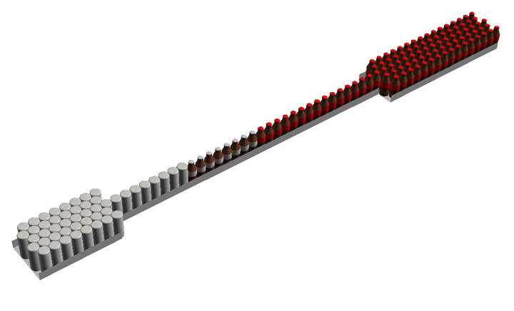
The MFC can draw all flow items the same, or sections can draw their own 3D shape or color of the flow items in order to show changes in the flow item as it moves down the line. This can be useful for showing the state the flow item is in. For example, a flow item may start as a small disk, or piece of plastic, that is then blown into a plastic bottle. The bottle can then be filled with liquid and a cap placed on top. Finally a label could be added to the bottle. This can all be done in a single MFC object with multiple sections, one for each state of the flow item.
Sections and Appended Sections
Sections
The MFC is made up of different sections. Each section can be straight or curved. It has its own length and vertical rise; its own speed and visualization properties. Since each section can have its own speed, it may move flow items along its length at a different rate than other sections.
Appended Sections
Each section can define any number of appended section. An appended section does not have its own speed, and as such, cannot be connected to a motor. Instead, it inherits its speed from its parent section. Additionally, appended sections cannot have decision points. Appended sections are specifically designed to increase the speed of moving flow items along the MFC. This is because the flow items on a appended section move with the flow items on the parent section.
Appended sections can still define their physical layout; from length, vertical rise, number of lanes and so on. If you have a section of conveyor that is simply moving flow items from point A to point B at a constant speed, appended sections are the way to go.
Underlying Logic and Crosslines
This next section is going to explain how the underlying logic of the MFC works. For most modellers, understanding this logic may not be necessary. However, it will help to explain how flow items are moved along the MFC and how to ensure greater accuracy or faster run speeds.
Timer Events
As explained above in Sections and Appended Sections, each section can have its own speed. This means that each section will create its own set of events that will move flow items along the MFC, like a ticker. The more sections there are, the more ticks or events will be created, the more the FlexSim engine has to compute. Appended sections move at the same time as their parent section, so no events will be created by appended sections.
Crosslines
When the model is reset, the MFC loops through all of its sections and calculates the physical length of that section. It then takes the Bottle Diameter, as defined in the MFC properties, and divides the length by the bottle diameter. The result is the number of crosslines for that section. Each crossline can hold one flow item per lane. Below is an image showing a series of crosslines. Each colored line represents a different crossline.
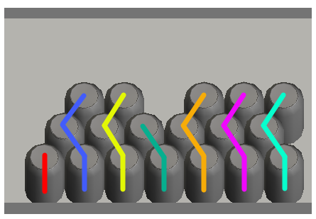
You'll note that the crosslines are not straight across. Instead, they pack the flow items in order to fit the maximum number of flow items in each section.
When a section's timer event fires, each crosslines content moves to the next crossline. If there is insufficient space in the next crossline, only some or none of the flow items will be moved. This then causes the flow items to back up and fill additional lanes.
Crossline Multiplier
Each section can define a Crossline Multiplier (appended sections inherit from their parent section). The crossline multiplier gives you control over how large or small each crossline is. By default the crossline multiplier is set to one, meaning each crossline is the width of one flow item. If speed is important, increases the crossline multiplier to two or more will reduce the number of events for that section. It will also decrease the accuracy of moving flow items from one section to another. This accuracy is determined by the speed of the section and the bottle diameter.
To better explain, start with a crossline multiplier of one, a section length of one meter and a speed of 0.1 meters per second. If the bottle diameter is set to 0.1 meters there will be 10 crosslines in the section. If the flow item enters the section at time 0, it will take 10 seconds and 10 ticks (events) for the flow item to move all of the way across the section. In this simple case the accuracy is 100%. Now take this same case and change the crossline multipler to three. This will cause each crossline to be the width of three bottle diameters. Each tick, or timer event, will move the flow item 0.3 meters. It will take the flow item three ticks to leave the section which will occur at 9 seconds. The accuracy of the flow item's movement down the MFC has decreased, but we have also decreased the number of events the engine has to execute and so, decreased the execution time.
On the other side, you can increase the accuracy of your section by setting the crossline multiplier to something less than one. If we use the example above and change the crossline multiplier to 1/2 then each crossline will be the width of half of a bottle diameter or 0.05 meters. Each tick will be at 0.5 seconds and will move the bottle 0.05 meters. This will double the number of events it takes to move flow items from start of the section to the end, but it will also increase the accuracy and ensure that the flow items exit the section and the right time.
Motors
Motors can be used to control the speeds of multiple MFC sections. When the motor's speed is changed, all connected sections will change to the motor's speed. If the motor is stopped either through code, a Time Table or MTBF/MTTR object, all of the motor's connected sections will also stop.
Decision Points
Decision points can be used to execute logic as flow items move through the MFC. When a decision point is positioned along the section, it uses the data from the crossline located at the decision point for calculating its state and firing triggers. Custom code can be written for the triggers or there is a standard list of pick options as well as some MFC specific pick options for controlling the decision point's color as well as section/motor speeds.
Decision points fire events as their state changes which allows you to tie Process Flow activities to the decision points like the Event-Triggered Source and Wait for Event.