Kinematics
Overview and Key Concepts
FlexSim's kinematics functionality allows you to have a single object perform several travel operations through one common interface. Each travel operation can have its own acceleration, deceleration, startspeed, endspeed, and maximum speed properties. Travel operations can overlap with each other, or be performed in sequence.
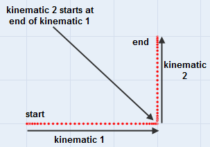
Below is a time-based plot of two kinematics performed in sequence:
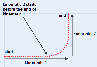
And a time-based plot of two kinematics that overlap each other:
Kinematics can also be used just to make it easier to handle the math for any logic that involves speeds, rates, accelerations, decelerations, etc.
As an example, an overhead crane usually has several motors that drive it. One motor drives the bridge along a railing, while another motor drives a trolley along the bridge, while another lifts the hook or grabber by a cable. Each of these motors may have their own acceleration, deceleration, and maximum speed properties. Using kinematics, you can define all of these motions through a single kinematics interface, where different motors can work simultaneously, giving the motion of the crane's end effector a very dynamic behavior. Before kinematics were introduced, the simplest way to simulate this behavior was to have three different objects hierarchically ordered in the model tree, each object simulating one motion or kinematic. While this works very well in some cases, in other instances it can become tedious and unfriendly. Kinematic functionality attempts to fix this problem by allowing one object to do several motions or kinematics simultaneously.
Commands Overview
The following is a summary of the kinematics commands:
- initkinematics - This initializes data for the kinematics, saving things like the start location and rotation of the object you want to apply motion to.
- addkinematic - This gives travel/rotate operations to the object. For example, you can tell the object, starting in 5 seconds and travel 10 units in the x direction, with a given acceleration, deceleration, and max speed. Then you can tell the object, starting in 7 seconds, travel 10 units in the y direction, with a different acceleration, deceleration, and max speed. The effect of these two operations is that the object will start traveling in the x, then will start simultaneously accelerating in the y, following a parabolic curved path to the destination. Each call to addkinematic will add another operation to the object.
- updatekinematics - This command should be called when the object is being redrawn. This calculates the current position and rotation of the kinematics based on the current time, and sets the object's location to that position.
initkinematics
- The Blank Node - For the initkinematics command, as well as all other kinematics commands, you must pass a reference to a blank node as the first parameter. This specifies where you want kinematic information to be stored, or, if you are getting information out of it, where kinematic information has been stored. The node needs to be an otherwise unused node, so that kinematic functionality can store data as needed. For modelers, this node will most likely be a label. Once kinematics have been initialized, the node will display the text "do not touch". This node should not be clicked on in a tree or table view while a kinematic operation is in process, or the kinematic data may be corrupted.
- Overloading - The initkinematics command is overloaded, so you can call initkinematics with two different parameter sets, depending on your situation. Parameters for these two overloads are as follows.
void initkinematics(treenode datanode, treenode object [, int flags])
- datanode - This is the blank node for kinematic data.
- object - This is the object that will do the moving.
- flags - This optional parameter defines various flags
for the kinematic. It can be a bitwise or on the following values:
- KINEMATIC_MANAGE_ROTATIONS - If this flag is set, the object will always point in the direction of travel.
- KINEMATIC_RELATIVE_LOCS - If this flag is set, then the object will travel according to its local coordinate system, based on the rotation of the object at the time you initialize the kinematic. If not, kinematic coordinates are based on the object's container's coordinate system.
- KINEMATIC_DO_NOT_PRUNE - By default, the kinematics logic will "prune" the kinematics as they go, meaning when you update the kinematics to a time that is after the end time of a given kinematic then it will remove that kinematic from the kinematics list. If you do not want it to do this, i.e. you may be doing queries across various times in the kinematic, then you should set this flag.
- KINEMATIC_RESET_BUFFER - By default, the kinematic's memory allocation is optimized for speed, i.e. it will only reallocate memory when it needs it, and it will not resize back down when you initialize the kinematic. However, if this flag is set, it will resize its data buffer to an initial size when initialized.
This parameter set assumes you have an object that you want to move, like a transporter. The first parameter, again, is a blank node kinematic data, either a label, attribute, or variable. The second parameter is the object that will do the moving. The command will save off the object's initial location and rotation. The optional parameter managerotation is either 1 or 0. If 1, the rotation of the object will be set according to the velocity of the object at any given time. By default, the object's positive x direction will always point in the direction of the object's current velocity. This would be used, for example, if you have a truck that you always want to point forward as it travels. If managerotation is passed as 0, then the object won't rotate unless given commands to rotate, which will be explained later. If you do not specify this parameter, then by default, managerotate is set to 0. The optional localcoords parameter specifies the orientation of subsequent travel command locations. For example, if my truck is rotated 45 degrees, and I want it to travel 5 units in the x direction, this can be interpreted in two different ways. Do I want it to travel 5 units in x according to the truck's coordinate system, or 5 units in x according to the model's coordinate system (or the coordinate system of the truck's container)? In the former case, the object would actually travel 3.5 units in the x direction and 3.5 units in the y direction according to the model's coordinate space. In the latter case, however, the object would travel the usual 5 in the x direction according to the model's coordinate space. The localcoords parameter specifies which coordinate system you want to use. If 1 is passed, the object's coordinate system will be used (the former case). Note that only the object's initial coordinate system will be used to calculate locations, not subsequent coordinate systems if the object rotates later on in the kinematics. If 0 is passed, the object's container's coordinate system will be used (the latter case). If you do not specify this parameter, the default is 0.
void initkinematics(treenode datanode [, double x, double y, double z, double rx, double ry, double rz, int flags] )
- datanode - This is the blank node for kinematic data.
- x, y, z - These are optional initial location variables. Defaults: 0, 0, 0
- rx, ry, rz - These are optional initial rotation variables. Defaults: 0, 0, 0
- flags - See the first overload above for more information.
This parameter set allows you to explicitly pass initial locations and rotations, instead of referencing an object. Although you would probably more often use the other parameter set where you pass the object in, this parameter set gives you ultimate flexibility. Use this if you want to explicitly pass in the initial locations and rotations of the object, or if your location and rotation values don't necessarily represent real locations and rotations in your model. For example, you are simulating a robot arm, and there are several joints of the arm that move/rotation with different acceleration/deceleration/max speed values. The visualization of movements of the arm are not simulated with explicit Flexsim locations/rotations, but are done using your own draw commands and labels or variables. In this case, you don't want kinematics to be applied to straight rotations and locations, but rather to information that you are keeping on the object yourself. In such situations, a given set of kinematics does not need to be viewed as applied directly to x,y,z locations and x,y,z, rotations, but can rather be viewed as six separate kinematic motions, each along one axis. These six axes can represent whatever you want them to. For example, your robot has four joints, each with one rotation value. To have the four joints of the robot move using kinematics, you can have each joint simulate one axis in the kinematics. The x part of the kinematics applies to the rotation of joint 1, the y part applies to the rotation of joint 2, the z part applies to the rotation of joint 3, and the rx part applies to the rotation of joint 4. The other two parts of the kinematics, ry and rz, you don't worry about. You can initialize the kinematics with the start rotations of each of your 4 joints, and then add kinematics that apply to each joint individually. Then, when you want to get the joints' current rotation values out later to draw the robot arm in motion, you can use the getkinematics command instead of the updatekinematics command to get the values explicitly, and not have them be applied to an object's location or rotation. These commands will be explained later.
void setkinematicsrotoffset(treenode datanode, double rx, double ry, double rz)
- datanode - This is the blank node for kinematic data.
- rx, ry, rz - These are initial rotation variables.
This command would only be used if managerotation is passed into initkinematics as 1. This allows you to set an initial rotation from which the rotation is managed. By default, the object's positive x direction will always point in the direction of the object's current velocity. In the case of a truck, you may want the truck, instead of always being rotated so that it is traveling forward, to travel backward. Here you could specify a rotation offset of (0,0,180).
addkinematic
double addkinematic(treenode datanode, double x, double y, double z, double targetspeed [, double acc, double dec, double startspeed, double endspeed, double starttime, int type ] )
- datanode - This is the blank node for kinematic data.
- x, y, z - These are offset locations or rotations.
- targetspeed - This is the target travel speed.
- acc - This optional parameter specifies the acceleration. Default: 0 (or infinite acceleration)
- dec - This optional parameter specifies the deceleration. Default: 0 (or infinite deceleration)
- startspeed - This optional parameter specifies the initial velocity. Default: 0
- endspeed - This optional parameter specifies the ending velocity. Default: 0
- starttime - This optional parameter specifies the absolute start time. Default: Current Time
- type - This optional parameter specifies the type of travel to apply (rotation or travel). Default: KINEMATIC_TRAVEL
This command adds a kinematic to the set of kinematics. The x, y, and z parameters make up an offset location or rotation. For example, the location (5,5,0) tells the kinematic to travel 5 in the x and 5 in the y. Note that these are offsets from the object's current position, and not absolute locations. The targetspeed parameter specifies the target speed for the travel operation. The other parameters are optional. Acc specifies the acceleration. Dec specifies the deceleration. Startspeed specifies the speed that the kinematic should start at. If this speed is higher that the target speed, then the object will start at the start speed and decelerate down to the target speed. Endspeed specifies the ending speed for the operation. If endspeed is greater than targetspeed, then at the end of the operation, the object will accelerate from the target speed to the end speed. The starttime is the start time of the kinematic, in simulation time, not as an offset from the current time. The type parameter specifies what type of kinematic it is. This value will usually either be KINEMATIC_TRAVEL, or KINEMATIC_ROTATE. If it is KINEMATIC_TRAVEL, the operation will be applied to the x, y, and z location values. If it is KINEMATIC_ROTATE, the operation will be applied to the rx, ry, and rz rotation values, and speeds are defined in degrees per unit of time, accelerations/decelerations in degrees per unit of time squared. The command returns the time that this kinematic operation will finish.
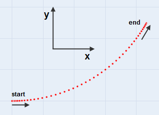
Below is a time-based plot of a kinematic that travels 3 in the x and 2 in the y, with accelerations and decelerations.
Turn Kinematic Types
In addition to KINEMATIC_TRAVEL and KINEMATIC_ROTATE, there are three "turn" kinematic types, which cause the moving object to turn a certain angle with a given turn radius. These are KINEMATIC_TURN_XY, KINEMATIC_TURN_YZ, and KINEMATIC_TURN_ZX. For these kinematic types, the x, y, and z parameters that you pass into addkinematic() take on a different meaning, as follows:
- x - The start angle in degrees. An angle of 0 means the initial direction of motion when the turn starts will be in the same direction as the first axis of the kinematic type's name, i.e. start angle 0 for KINEMATIC_TURN_XY means the initial motion is positive along the x axis, where for KINEMATIC_TURN_YZ the initial motion would be positive along the y axis. Use the right hand rule around a given axis when figuring out start and turn angles.
- y - The turn angle in degrees. The motion of the object will turn this number of degrees, parallel to the plane defined by the two axes in the kinematic type's name, i.e. KINEMATIC_TURN_XY will turn in the x/y plane, i.e. around the z axis.
- z - The turn radius in distance.
All other parameters are the same for this kinematic type, i.e. max speed, acceleration, deceleration, etc. Speeds are in length units per time unit, NOT in degrees per time unit.
As an example, if you would like to make a motion that turns from travelling positive along the x axis to travelling at 60 degrees off the x axis, with a turn radius of 5 (i.e. turn about the z axis), call:
		addkinematic(kinematics, 0, 60, 5, 1, 1, 1, 0, 0, time(),
		KINEMATIC_TURN_XY);
updatekinematics
void updatekinematics(treenode datanode, treenode object [, double updatetime])
- datanode - This is the blank node for kinematic data.
- object - This is the object that will do the moving.
- updatetime - This optional parameter specifies the absolute update time. Default: Current Time.
This command should be called in the middle of the kinematic operation, usually on predraw or draw. It calculates and then sets the current location and rotation of the object, according to all kinematics that have been added and the current update time. The updatetime parameter is optional. If it is not passed, the current simulation time is used.
Other Kinematics Commands
double getkinematics(treenode datanode, int type [, int kinematicindex, double updatetime/traveldist])
- datanode - This is the blank node for kinematic data.
- type - This specifies the type of information to retrieve (listed below).
- kinematicindex - This optional parameter specifies which kinematic to query. Default: 0 (all kinematics)
- updatetme/traveldist - This optional parameter represents either the update time or the travel distance, depending on the parameter type. Default: Current Time.
This command is used if you want to get explicit information on the kinematics. You can get information on the entire set of kinematics, or on each individual kinematic. Use this if your kinematics do not apply directly to object locations and rotations, or if you need this information in your logic. The type parameter specifies the type of information you want, and will be explained shortly. The kinematicindex parameter is optional, and specifies which individual kinematic you want to get information for. For example, if you add a kinematic to travel 5 units in the x direction as the second addkinematic command, you would pass a 2 as the kinematicindex parameter into the getkinematics command. If not passed, or if you pass a 0 value here, the default gets information for all kinematics together. The updatetime/traveldist parameter is optional. The meaning of this parameter depends on the type parameter you specify. Sometimes this parameter will not be used. Some of the time it represents the requested update time that you want to get information for. If not passed, the current time is used. In the case of a KINEMATIC_ARRIVALTIME query, this parameter instead represents travel distance. The use of this parameter will be explained with each query type.
| Information | Value of type Parameter | Single Kinematic | All Kinematics |
|---|---|---|---|
| Location | KINEMATIC_X KINEMATIC_Y KINEMATIC_Z |
These return x, y, or z component of the current location of the specified kinematic at the given update time. For example, if you added a kinematic to travel 10 units in the x, starting at time 5, and you want to know the x location for this given kinematic at time 7, you can call getkinematics(datanode, KINEMATIC_X, index, 7) to get the x location for time 7. | These return the x, y, or z location of the object at the given update time. |
| End Distance | KINEMATIC_ENDDIST | This returns the distance from the final destination location of all kinematics from the object's initial location. Here the updatetime parameter is not used. | |
| Total Distance | KINEMATIC_TOTALDIST | This returns the total distance for the kinematic operation. | This returns the sum of the distances of all the added kinematics. This has a
subtle difference from KINEMATIC_ENDDIST. For example, if your first kinematic travels 10 in the x direction, and your second kinematic travels -10 in the x direction, then the enddist value will be 0, whereas the totaldist value will be 20. Here the updatetime parameter is not used. |
| Total Component Distances | KINEMATIC_TOTALX KINEMATIC_TOTALY KINEMATIC_TOTALZ |
These return the x, y, or z component of the total distance for the kinematic operation. These are the same values you passed into the addkinematic command. Here the updatetime parameter is not used. | These return the sum of x, y, or z component of all added kinematics. Here the updatetime parameter is not used. |
| Cumulative Distance | KINEMATIC_CUMULATIVEDIST | This returns the cumulative travel distance of all added kinematics. Unlike enddist or totaldist, it calculates the distance of the possibly curved path that the object will follow during the entire kinematic operation. Here the updatetime parameter is not used. Note: for cumulative distance, if you are using turn kinematics, the turn kinematics may not overlap other travel or turn kinematics. If they overlap with others, then the cumulative distance calculation will be incorrect. | |
| Velocity | KINEMATIC_VX KINEMATIC_VY KINEMATIC_VZ |
These return the x, y, or z component of the current velocity for the specified kinematic at the given update time. | These return the x, y, or z velocity of the object for the given time. |
| Start Speed | KINEMATIC_STARTSPEED | This returns the start speed for the kinematic. This is the startspeed you specify in the addkinematic command. Here the updatetime parameter is not used. | |
| Peak Speed | KINEMATIC_PEAKSPEED | This returns the peak speed or "reached speed" for the kinematic. This is usually the same as the target speed specified in the addkinematic command, but may not be if the kinematic cannot get to the target speed given the distance it has to travel. Here the updatetime parameter is not used. | |
| End Speed | KINEMATIC_ENDSPEED | This returns the end speed for the kinematic. This is usually the endspeed that you specify in the addkinematic command, but may not be if the kinematic cannot decelerate/accelerate to your specified endspeed given the distance it has to travel. Here the updatetime parameter is not used. | |
| Total Velocity | KINEMATIC_VELOCITY | This returns the total velocity of the kinematic for the given time. | This returns a scalar value of the total velocity for the given time. |
| Acceleration (Starting) | KINEMATIC_ACC1 | This returns the acceleration value used to get from the start speed to the target speed. If the start speed is less than the target speed, then this value will be the acceleration value. Otherwise it will be the negative deceleration value. Here the updatetime parameter is not used. | |
| Acceleration (Stopping) | KINEMATIC_ACC2 | This returns the acceleration value used to get from the target speed to the end speed. If the end speed is less than the target speed, then this will return the negative deceleration value. Otherwise it will return the acceleration value. Here the updatetime parameter is not used. | |
| Rotation | KINEMATIC_RX KINEMATIC_RY KINEMATIC_RZ |
These return the x, y, or z rotation of a rotational kinematic at the given update time. | These return the x, y, or z rotation of the object at the given update time. This will only work if rotations are managed manually. |
| End Rotational Distance | KINEMATIC_ENDRDIST | This returns the distance from the final destination rotational position of all kinematics from the object's initial rotational position. This will only work if rotations are managed manually. Here the updatetime parameter is not used. | |
| Total Rotational Distance | KINEMATIC_TOTALRDIST | This returns the total rotational distance for the kinematic operation if it is a rotational kinematic. | This returns the sum of the rotational distances of all the added kinematics. This will only work if you are managing rotations yourself. Here the updatetime parameter is not used. |
| Total Component Rotations | KINEMATIC_TOTALRX KINEMATIC_TOTALRY KINEMATIC_TOTALRZ |
These return the x, y, or z component of the total rotational distance for the kinematic operation if it is a rotational kinematic. These are the same values you passed into the addkinematic command. Here the updatetime parameter is not used. | These return the sum of rx, ry, or rz component of all added kinematics. This will only work if you are managing rotations yourself. Here the updatetime parameter is not used. |
| Cumulatvie Rotational Distance | KINEMATIC_CUMULATIVERDIST | This returns the cumulative rotational travel distance of all added kinematics. This will only work if you are managing rotations yourself. Here the updatetime parameter is not used. | |
| Rotational Velocity | KINEMATIC_VRX KINEMATIC_VRY KINEMATIC_VRZ |
These return the x, y, or z component of the current rotational velocity for the specified kinematic at the given time if it is a rotational kinematic. | These return the rotational x, y, or z velocity of the object for the given time. |
| Total Rotational Velocity | KINEMATIC_RVELOCITY | This returns the total rotational velocity of the kinematic for the given time if it is a rotational kinematic. | This returns a scalar value of the total rotation velocity for the given time. This only works if rotations are managed manually. |
| Start Times | KINEMATIC_STARTTIME | This returns the time that the specified kinematic will start its operation. This is the same starttime that you specified when you added the kinematic. Here the updatetime parameter is not used. | This returns the lowest start time of all the kinematics. Here the updatetime parameter is not used. |
| Acceleration Time (Starting) | KINEMATIC_ACC1TIME | This returns the total time the kinematic will spend accelerating/decelerating from the start speed to the target speed. Here the updatetime parameter is not used. | |
| Arrival Time | KINEMATIC_ARRIVALTIME | In this query, the updatetime/traveldist parameter is used as a requested travel distance for the given kinematic. This returns the time of arrival for a certain sub-distance of a given kinematic. For example, if I've added a kinematic that tells the object to travel 5 units in the x direction, but I want to know how long it will take him to travel just 3 of those 5 units, I can use this query, and pass 3 in as the traveldist parameter. | |
| Peak Time | KINEMATIC_PEAKTIME | This returns the total time the kinematic will spend traveling at the peak speed. Here the updatetime parameter is not used. | |
| Acceleration Time (Stopping) | KINEMATIC_ACC2TIME | This returns the total time the kinematic will spend accelerating/decelerating from the target speed to the end speed. Here the updatetime parameter is not used. | |
| End Times | KINEMATIC_ENDTIME | This returns the time that the specified kinematic will finish its operation. This is the same endtime that is returned from the addkinematic command. Here the updatetime parameter is not used. | This returns the highest end time of all the kinematics. Here the updatetime parameter is not used. |
| Number of Kinematics | KINEMATIC_NR | This returns the number of kinematics that have been added. Here the updatetime parameter is not used. | |
| Turn Kinematic Data | KINEMATIC_STARTANGLE KINEMATIC_TURNANGLE KINEMATIC_TURNRADIUS |
These return the start angle, turn angle, and turn radius of a turn kinematic. | |
| Kinematic Type | KINEMATIC_TYPE | This returns KINEMATIC_TRAVEL if the specified kinematic is a travel operation, and KINEMATIC_ROTATE if the kinematic is a rotate operation. |
void profilekinematics(treenode datanode [, int index ])
- datanode - This is the blank node for kinematic data.
- index - This optional parameter specifies the index of a specific index to print information for. Default: 0 (all kinematics)
This command prints kinematic information to the output console. The index parameter is optional. If it is not passed, then information will be printed for all kinematics that have been added. If it is passed, then the index variable is an index of the added kinematic you want to print information for.
void deactivatekinematics(treenode datanode)
- datanode - This is the blank node for kinematic data.
This command tells the kinematic to not update locations when the updatekinematics command is called. Execute this on reset to free the object to move it around in the ortho view.