Working With A* Navigation
Introduction
You can use the A* navigation tool (pronounced "AStar") to create travel barriers for task executers. Any fixed resources you connect to the A* system will also be treated as a barrier that cannot be passed through directly. When a task executer needs to travel from one point to another, the A* Navigator will then use these barriers and the travel threshold around fixed resources to calculate the shortest distance between the two points.
Before reading this topic, you should make sure you are familiar with the concepts discussed in Key Concepts About Travel. This topic will provide a high-level overview of how A* navigation works.
The rest of this topic will provide instructions about how to do the various tasks needed to build an A* navigation system.
Connecting 3D Objects to the A* Navigator
After you've added an A* navigator to your model, you need to connect it to all the task executers that will use the navigation system. You also need to add any fixed resources to the model that should be treated as barriers that task executers can't walk through.
To connect 3D objects to the A* navigator:
- You can connect the A* navigator to 3D objects using the same method you'd use to
create input/output port connections (A-connects) between fixed resources. Click the
Connect Objects button
 on the toolbar to
open a menu. Select Connect Objects from the menu to turn
on connection mode.
on the toolbar to
open a menu. Select Connect Objects from the menu to turn
on connection mode. - When you are in connection mode, your mouse pointer will change to a plus sign with
a chain link symbol next to it:

- Once you are in connection mode, click the AStar Navigator. You will notice as you move your mouse that a yellow line will appear between the navigator and your cursor.
- Click a 3D object to connect it to the navigator. Once it's connected, a purple colored space will appear under the connected object.
- You will still be in connection mode even after you connect the navigator to an object. If you need to exit connection mode, press the Esc key or right-click a blank area in the model. Otherwise, you can continue connecting network nodes together if needed.
Adding Dividers and Barriers
You can add dividers and/or barriers to your 3D model in order to create obstacles that will cause the task executer to travel around them. Dividers can act like walls, as shown in the following example:
Barriers can restrict an entire area in the grid:
Adding Dividers
To add dividers to a model:
- In the Library under the A* Navigation group, click the
Divider object to enter Create Divider mode. Your mouse
pointer will change to the Dividers icon
 to show that you are in Create Dividers
mode.
to show that you are in Create Dividers
mode. - Find the position in your simulation model where you want to place a divider. When you click that position in the model and start moving the mouse pointer in a different direction, you'll notice that it begins creating a divider. Reposition the mouse pointer until the divider's end is the approximate length, angle, and radius you want it to be relative to the starting point. Click the mouse again to finish creating the divider.
- If needed, you can move the endpoints and connecting points to change the divider's length, angle, or radius.
- Press Esc or right-click a blank space in the model to exit Create Divider mode.
Adding Barriers
To add a barrier to a model:
- In the Library under the A* Navigation group, click the
Barrier object to enter Create Barrier mode. Your mouse
pointer will change to the Barrier icon
 to show that you are in Create Barriers mode.
 - Find the position in your simulation model where you want to place a barrier. When you click that position in the model, a red diamond will appear. Once you start moving the mouse pointer in a different direction, you'll notice that it begins creating a barrier. Reposition the mouse point until the barrier's is the approximate length and width you want it to be. Click the mouse again to finish creating the divider.
- If needed, you can click the barrier's red resizing arrows to change the length or width of the barrier.
- Press Esc or right-click a blank space in the model to exit Create Barrier mode.
Defining Barrier Travel Patterns
By default, a barrier acts as a solid barrier that no one can travel in. However, you can also define a barrier as an area of one or more travel patterns. For example, you could define a barrier such that travelers may only travel one way while inside the barrier. As another example, you could set up a barrier so that travelers travel in one direction when on the right side of the barrier, and in the opposite direction when on the left side of the barrier.
To define barrier travel patterns:
- Create a barrier as described above.
- Click on the barrier. Several manipulation handles will appear.
- To define a specific pattern, click on one of more of the four arrows in the center of the barrier. This will change the arrow color to green, indicating that travel is allowed in that direction.
- To define multiple separate pattern areas within the barrier, click on a scissor icon on the edge of the barrier. This will split the area into two separate areas, each with its own four pattern arrows in the center. Then click the arrows to define the travel pattern for each area.
- To change the size of pattern areas, click and move the dividing lines, or use the red sizer arrows shown over the dividing lines on the edge of the barrier.
- To remove areas that have been created, click the merge button on the edge of the barrier to merge two adjacent areas together.
Adding One-Way Dividers
A divider can be a one-way divider, meaning that a task executer can pass through a divider in one direction, but cannot pass through in another direction. The green arrows on the one-way divider indicate which direction the task executer can travel:
To add a one-way divider, you'll use the same method you would use to add a normal divider. Once you've created the divider, click on the object, and in Quick Properties, uncheck Two Way.
Troubleshooting Travel Thresholds
Before reading this section, you'll want to make sure you've read the key concepts about A* Travel Thresholds to understand how they work.
One of the most typical problems you might have with A* navigation is with task executers traveling to a place on the grid that you didn't expect or taking a strange route to a fixed resource. Usually, this is caused by problems with travel thresholds that extend beyond barriers or dividers.
To troubleshoot this problem:
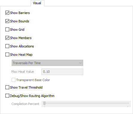
- Double-click the AStar Navigator in the 3D model to open its properties window.
- On the Visual tab, check the Show Travel Threshold checkbox.
- Click OK to save the changes and close the properties window.
- On the simulation control bar, press the Reset button to apply the visual changes.
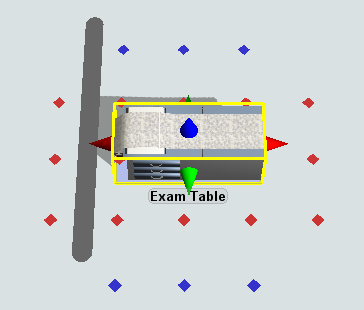
- Click a fixed resource that is located close to barriers or dividers to select it. Check that the object's calculated path zone (the red points) do not extend beyond the barriers or dividers. The following image shows an example of an object in which the red points extend beyond the divider beside it:
- Reposition the fixed resource until the red points are contained on the correct side of the divider or barrier.
Adding Preferred Paths
A preferred path gives more weight to a particular path when the A* algorithm is calculating the most efficient path for a task executer to use to get from one point to another.
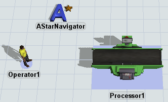
The following image shows a task executer's travel path before a preferred path has been applied:
As you can see, the task executer takes the upper path to get from the queue to the processor. Imagine that you wanted the task executer to take the lower path instead. You could create that logic by adding a preferred path:
Be aware that the preferred path acts a little bit like a magnet. A task executer will only use the preferred path if it is close enough to influence the task executer's current travel trajectory. Once the task executer gets close to it, it will begin to incorporate the preferred path in the travel calculations.
Notice also in the preceding image that the task executer only uses the preferred path when traveling in one direction. To make the task executer use it going in both directions, you'd have to add a second preferred path going in the opposite direction.
To add a preferred path:
- In the Library under the A* Navigation group, click the
Preferred Path object to enter Create Preferred Path mode.
Your mouse pointer will change to the Preferred Path icon
 to show that you are in Create
Preferred Path mode.
to show that you are in Create
Preferred Path mode. - Find the position in your simulation model where you want to place a preferred path. When you click that position in the model and start moving the mouse pointer in a different direction, you'll notice that it begins creating a preferred path. Reposition the mouse pointer until the preferred path's end is the approximate length, angle, and radius you want it to be relative to the starting point. Click the mouse again to finish creating the preferred path.
- Press Esc to exit Create Preferred Path mode.
- If needed, you can move the endpoints and connecting points to change the preferred path's length, angle, or radius.
Adding Bridges
Bridges can be used to allow an operator to pass through a barrier as needed. In simulation terms, this can represent a task executer possibly walking over a barrier using stairs or some other kind of bridge.
The following image shows what would happen in the A* system if you prevented a task executer from reaching its destination by placing too many barriers in its path:
Notice that the task executer is considered as having arrived once it reaches the closest possible point to its destination. It unloads the item at the processor even though it is not very close to the processor. If you wanted the task executer to get closer to the processor, you could add a bridge:
However, notice that now the task executer gets trapped on the other side of the dividers now. The task executer gets trapped because the bridge only goes one way. You can fix this problem by adding a second bridge going in the other direction:
To create a bridge:
- In the Library under the A* Navigation group, click the
Bridge object to enter Create Bridge mode. Your mouse
pointer will change to the Bridge icon
 to show that you are in Create Bridge mode.
 - Find the position in your simulation model where you want to place a bridge. When you click that position in the model and start moving the mouse pointer in a different direction, you'll notice that it begins creating a bridge. Reposition the mouse pointer until the bridge's end is the approximate length, angle, and radius you want it to be relative to the starting point. Click the mouse again to finish creating the bridge.
- Press Esc to exit Create Bridge mode.
- If needed, you can move the endpoints and connecting points to change the bridge's length, angle, or radius.
Adding Mandatory Paths
Mandatory paths can be used to force a traveler to only travel along designated paths in the system. For example, you may have a travel area that includes both humans and automated guided vehicles (AGVs). While the humans do not usually have designated paths to travel on, AGVs do. Here one option is to use the AGV module for AGVs, and use A* for humans. The problem with this option, however, is that AGV traffic would be blind to human traffic and vice versa. Thus objects may run over each other. Alternately, by defining mandatory paths in the A* travel area, and telling AGVs to only travel on mandatory paths, you can still simulate designated paths for AGVs, and both AGVs and humans would recognize and avoid each other because they share the same A* travel grid.
To create mandatory paths:
- In the Library under the A* Navigation group, click the
Mandatory Path object to enter Create Mandatory Path mode. Your mouse
pointer will change to the Mandatory Path icon
 to show that you are in Create Mandatory Path mode.
 - Find the position in your simulation model where you want to place a mandatory path. When you click that position in the model and start moving the mouse pointer in a different direction, you'll notice that it begins creating a mandatory path. Reposition the mouse pointer until the path's end is the approximate length and angle you want it to be relative to the starting point. Click the mouse again to finish creating the bridge.
- Press Esc to exit Create Mandatory Path mode.
- If needed, you can move the endpoints and connecting points to change the bridge's length, angle, or radius.
- Once you've added mandatory paths, you need to designate which travelers are to travel only on mandatory paths. To do this, click on a task executer that has been added to the A* network. In the Quick Properties panel on the right, under A* Traveler check the box Use Mandatory Paths.
Adding Elevator Banks
An Elevator Bank can simulate a bank of elevators that moves people between different floors in a facility. In the context of A*, an elevator bank implements a special bridge between two or more A* grids that are stacked on top of each other along the z axis. In order to get from one floor/grid to another, a traveler will go to the elevator bank and make a request to that elevator bank. An elevator will then go to the traveler's floor, pick up the traveler, and take her/him to the desired destination floor.
To create an elevator bank:
- First create two or more vertically stacked A* grids. In the Library under the
A* Navigation group, click the
Grid object to enter Create Grid mode. Your mouse
pointer will change to the Grid icon
 to show that you are in Create Grid mode.
 - If you already see an A* grid on the ground level (a blue rectangular border surrounding A* barriers, dividers, etc.) then skip this step. To create the first grid, find the position in your simulation model where you want to place one corner of the grid. When you click that position in the model and start moving the mouse pointer in a different direction, you'll notice that it begins creating a grid. Reposition the mouse pointer until the grid surrounds the desired area in your model. Click the mouse again to finish creating the grid.
- Move the view's Grid Z up in the Z direction. First click in an empty area in your model. Then in Quick Properties under the View Settings pane, change the Grid Z value to the z position of the second floor, say 5 meters up. This will change the "base point" at which you are viewing the model, creating objects, etc.
- Again, find the position in your simulation model where you want to place one corner of the second floor grid. When you click that position in the model and start moving the mouse pointer in a different direction, it will create a new grid on the second floor. Reposition the mouse pointer until the grid surrounds the desired area in your model. Click the mouse again to finish creating the grid.
- Set back your view's Grid Z. Click in a blank area in the model, then in Quick Properties change the view's Grid Z back to 0.
- Now create the Elevator Bank. In the Library under the People group, drag a new Elevator Bank object into your model. Expand the object's x axis to make more elevators part of the bank.
- Use the standard A-connect mode to connect the Elevator Bank to the A* navigator object in the model, making the Elevator Bank part of the A* network.
Turning A* Visibility On or Off
After you've built your A* navigation system and validated that it works correctly, you might want to turn off the system's visibility to reduce the model's visual clutter. To turn off A* visibility:
- Double-click the AStar Navigator in the 3D model to open its properties window.
- On the Visual tab, clear all the checkboxes as needed.
Working With Large Task Executers
If you're working with a large task executer such as a transporter, you should be aware that the task executer might actually be larger than a single square on the A* grid. FlexSim will determine which square a task executer is on based on its center point. Depending on the size of your travel grid, this can sometimes create some strange problems with the 3D visuals.
These problems might become especially apparent when using collision avoidance. The A* navigator calculates collision avoidance purely based on the individual squares the travelers are moving on. This means that if a traveler's size takes up more than one square, this extra size will be ignored by the collision avoidance mechanism, and some travelers may overlap. You'll need to decide on the right balance between having a smaller square size and more precise travel, versus a larger square size and better collision avoidance.