Task 3.2 - Add Area Restriction PLC Logic
Task Overview
In this task, you'll learn how to use the Get Variable activity to get the state of a photo eye variable. You'll design an emulation system in which photo eyes will communicate with each other to restrict the flow of items to a specific area. The Get Variable activity will be used by photo eyes to determine whether the restricted area is clear and can receive flow items. If not, the motor will stop until the area is clear again.
When you're finished, the simulation model will work similar to the one shown in the following image:
Step 1 Edit the 3D Model
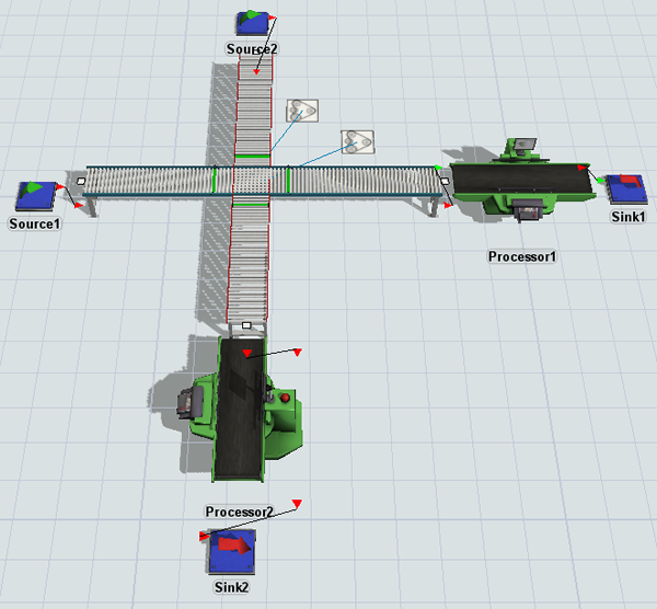
In this step, you'll edit the 3D model to add a second conveyor line that converges with the first. You'll also add a separate motor to control this conveyor as well as its own source, processor, and sink. Lastly, you'll make the two conveyors different colors so that you can easily distinguish between them visually. When you're finished, your model should look similar to the following image:
To build this model:
- Make sure your 3D model window is open and active. From the Library, drag the
following 3D objects into the model:
- A Source
- A Straight Conveyor (under Conveyors)
- A Processor
- A Sink
- A Motor (under Conveyors)
- Move the tail of Conveyor2 (the newly added conveyor) to rotate it 90 degrees so that it is perpendicular to the other conveyor.
- Move Conveyor2 so that it intersects with Conveyor1.
- Click Processor2 to select it. In Quick Properties,
change its Z-rotation
 to
to -90.00. - Add a Photo Eye (under Conveyors) to Conveyor1, placing it slightly after the intersecting Conveyor2.
- Add two additional Photo Eye objects to Conveyor2, placing one slightly before the intersecting Conveyor1 and one slightly after.
- For clarity, rename the photo eyes as follows:
- Create port-connections (A-connects) between the following objects:
- From Motor2 to Conveyor2
- From Source2 to Conveyor2
- From Conveyor2 to Processor2
- From Processor2 to Sink2
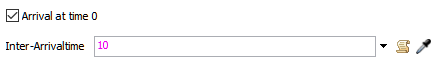
- Double-click Source2 to open its properties window. On the Source tab, check the Arrival at time 0 box.
- In the Inter-Arrivaltime box, delete the current text
and type
10. - In the Toolbox under the Conveyor System group, right-click ConveyorType1 to open a menu. Select Duplicate to create a copy of this conveyor type.
- Double-click the copied conveyor type to open its properties window.
- In the name box at the top, rename this conveyor type as ConveyorType2.
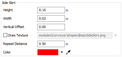
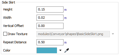
- On the Visual tab in the Side Skirt group, change the Color to red.
- Click the OK button to save the changes and close the window.
- In the Toolbox, double-click ConveyorType1 to open its properties window.
- On the Visual tab in the Side Skirt group, change the Color to light blue.
- Click the OK button to save the changes and close the window.
- In the 3D model, click Conveyor2 to select it. In Quick Properties, click the Conveyor Type menu and select ConveyorType2.
| Object | New Name |
|---|---|
| Photo eye before intersection on Conveyor1 | PhotoEye1A |
| Photo eye after intersection on Conveyor1 | PhotoEye1B |
| Photo eye before intersection on Conveyor2 | PhotoEye2A |
| Photo eye after intersection on Conveyor2 | PhotoEye2B |
Check that your simulation model looks similar to the image shown at the beginning of this step.
Step 2 Add Activities and Variables to the Process Flow
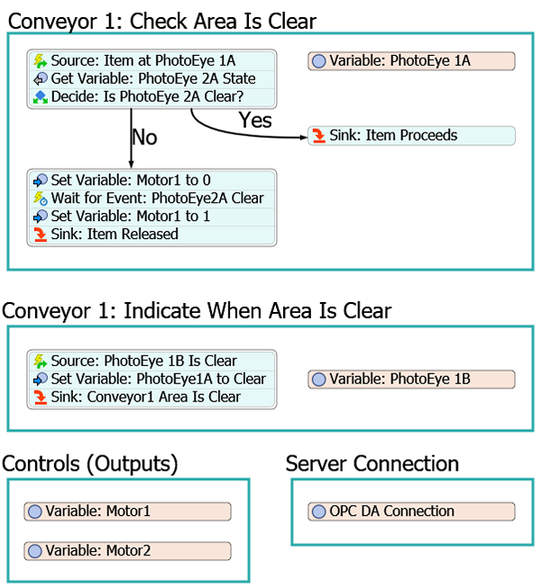
In this step, you'll edit the process flow that controls the simulation logic for the first conveyor. You'll add and rename several different shapes, activities, and emulation variables. When you're finished, your process flow should look similar to the following image:
For now, you'll merely add and connect these activities to the process flow. You'll edit the properties to add the functionality in a later step.
To add these activities and variables:
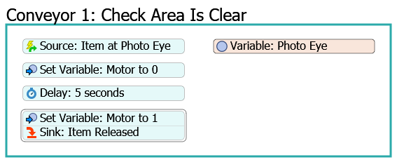
- With the process flow open and active, rename the Sensors (Inputs) shape as Conveyor 1: Check Area Is Clear.
- Directly under this shape, add another Process shape.
- Rename the new shape Conveyor 1: Indicate When Area Is Clear.
- In the Conveyor 1: Check Area Is Clear shape, click the
stacked block of activities and click the Unlink buttons
 to cut the links from the
Set Variable: Motor to 0 and the
Delay: 5 seconds activities so that they aren't connected
to the stacked block any more.
to cut the links from the
Set Variable: Motor to 0 and the
Delay: 5 seconds activities so that they aren't connected
to the stacked block any more. - Delete the Delay: 5 seconds activity.
- Create a new stacked block starting with the Source: Item at
Photo Eye activity. Add the following activities, appending them to end:
- A Get Variable (under Shared Assets)
- A Decide (under Basic)
- You'll create another stacked block, this time starting with the Set Variable: Motor to 0 activity. Add a Wait for Event (under Basic) after it.
- Add the stacked block starting with the Set Variable: Motor to 1 to the end of this stacked block.
- Create another stacked block with the following activities:
- An Event-Triggered Source (under Token Creation)
- A Set Variable (under Shared Assets)
- A Sink (under Basic)
- To the right of the activities, add a Sink (under Basic).
- Rename the activities and shared assets as follows:
- Create two connectors going out from the Decide: PhotoEye 2A Clear? activity. The first connector should go to the Set Variable: Motor1 to 0 activity. The second connector should go to the Sink: Item Proceeds activity.
- Click connector 1 to select it. In Quick Properties in the
Name box, type
No. - Click connector 2 to select it. In Quick Properties in the
Name box, type
Yes. - In the Conveyor 1: Indicate When Area Is Clear shape,
create a stacked block of activities with the following activities:
- An Event-Triggered Source (under Token Creation)
- A Set Variable (under Shared Assets)
- A Sink (under Basic)
- To the right of this new stacked block of activities, add a Variable (under Shared Assets).
- Rename these activities as follows:
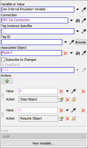
- In the Controls (Outputs) shape, click Variable: Motor to select it. Rename it Variable: Motor1.
- Press Ctrl+C to copy Variable: Motor1. Click a blank area in the shape and press Ctrl+V to paste the copy. Check that the new variable is named Variable: Motor2.
| Activity | New Name |
|---|---|
| Source: Item at Photo Eye | Source: Item at PhotoEye 1A |
| Get Variable | Get Variable: PhotoEye 2A State |
| Decide | Decide: Is PhotoEye 2A Clear? |
| Set Variable: Motor to 0 | Set Variable: Motor1 to 0 |
| Wait for Event | Wait for Event: PhotoEye2A Clear |
| Set Variable: Motor to 1 | Set Variable: Motor1 to 1 |
| Variable: Photo Eye | Variable: PhotoEye1A |
| Sink | Sink: Item Proceeds |
| Activity | New Name |
|---|---|
| Source | Source: PhotoEye1B Is Clear |
| Set Variable | Set Variable: PhotoEye1A to Clear |
| Sink | Sink: Conveyor1 Area Is Clear |
| Variable | Variable: PhotoEye 1B |
Consider saving your simulation model at this point.
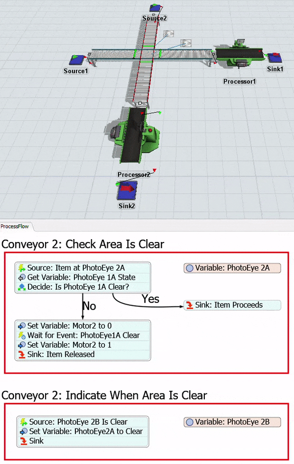
Step 3 Copy and Adapt the Logic for Conveyor 2
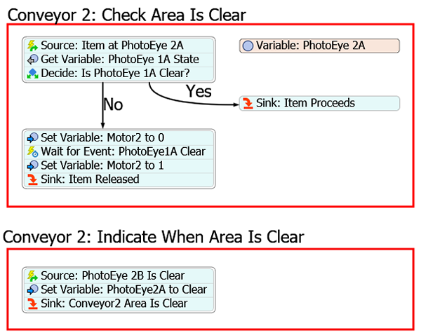
In this step, you'll copy the sections of the process flow that will control the simulation logic for the first conveyor and adapt it for the second conveyor. When you're finished, the copied sections of your process flow should look similar to the following image:
For now, you'll merely add and connect these activities to the process flow. You'll edit the properties to add the functionality in a later step.
To copy and rename these activities and variables:
- Click the Conveyor 1: Check Area Is Clear shape to select it. Press Ctrl+C to copy it. Click a blank area of the process flow and press Ctrl+V to create a copy.
- Rename the new copied shape Conveyor 2: Check Area Is Clear.
- In Quick Properties, change the Color of the newly copied shape to red (to match Conveyor2's color).
- In the Conveyor 2: Check Area Is Clear shape, rename the following activities and shared assets for clarity:
- Click the Conveyor 1: Indicate When Area Is Clear shape to select it. Press Ctrl+C to copy it. Click a blank area of the process flow and press Ctrl+V to create a copy.
- Rename the new copied shape Conveyor 2: Indicate When Area Is Clear.
- In Quick Properties, change the Color of the newly copied shape to red (to match Conveyor2's color).
- For now, just delete the Variable: PhotoEye 1B1 variable. You'll create this variable later.
- In the Conveyor 2: Indicate When Area Is Clear shape, rename the following activities and shared assets for clarity:
| Activity | New Name |
|---|---|
| Variable: PhotoEye 1A1 | Variable: PhotoEye 2A |
| Source: Item at PhotoEye 1A | Source: Item at PhotoEye 2A |
| Get Variable: PhotoEye 2A State | Get Variable: PhotoEye 1A State |
| Decide: Is PhotoEye 2A Clear? | Decide: Is PhotoEye 1A Clear? |
| Set Variable: Motor1 to 0 | Set Variable: Motor2 to 0 |
| Wait for Event: PhotoEye2A Clear | Wait for Event: PhotoEye1A Clear |
| Set Variable: Motor1 to 1 | Set Variable: Motor2 to 1 |
| Activity | New Name |
|---|---|
| Source: PhotoEye 1B Is Clear | Source: PhotoEye 2B Is Clear |
| Set Variable: PhotoEye1A to Clear | Set Variable: PhotoEye2A to Clear |
| Sink: Conveyor1 Area Is Clear | Sink: Conveyor2 Area Is Clear |
Consider saving your simulation model at this point.
Step 4 Update the Variable Links and Connections
In this step, you'll update all of the emulation variable shared assets so that they are connected to the OPC DA Connection variable. You'll also make sure all the variables are linked to the correct objects in the 3D model and that they have the correct settings. To make these updates:
- In the Controls (Outputs) shape, click Variable: Motor2 to select it. Ensure that when it is selected, it shows a blue line linking it to the OPC DA Connection variable.
- In Quick Properties next to the Associated Object box,
click the Sampler button
 to enter sampling mode.
 - In the 3D model, click Motor2 (the motor connected to the red conveyor) to sample it.
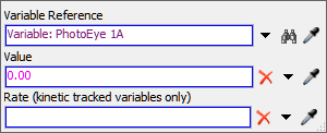
- In the Conveyor 1: Check Area Is Clear shape, click Variable: PhotoEye 1A to select it. Ensure that when it is selected, it shows a blue line linking it to the OPC DA Connection variable.
- In Quick Properties, check that the Associated Object
box reads
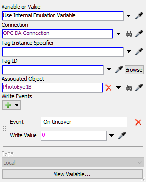
PhotoEye1A. - In the Write Events group next to the
On Uncover event, click the
Delete button
 to delete this event.
 - In the Conveyor 2: Check Area Is Clear shape, click Variable: PhotoEye 2A to select it. Ensure that when it is selected, it shows a blue line linking it to the OPC DA Connection variable.
- In Quick Properties next to the Associated Object box,
click the Sampler button
to enter sampling mode.
- In the 3D model, click PhotoEye2A (the first photo eye on the red conveyor) to sample it.
- In the Write Events group next to the
On Uncover event, click the
Delete button
to delete this event.
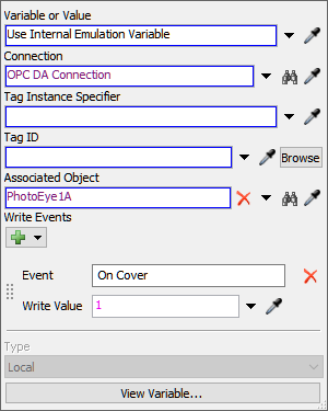
- In the Conveyor 1: Indicate When Area Is Clear shape, click Variable: PhotoEye 1B to select it. In Quick Properties, click the arrow next to the Variable or Value box to open a menu. Point to Internal Emulation Variable, then point to Sensors (PLC Inputs), and select OPC DA Tag.
- Next to the Connection box, click the
Sampler button
to enter sampling mode.
- In the Server Connection shape, click the OPC DA Connection variable to sample it.
- Next to the Associated Object box, click the
Sampler button
to enter sampling mode.
- In the 3D model, click PhotoEye1B (the second photo eye on the blue conveyor) to sample it.
- In the Write Events group, click the
Add button
 to open a menu. Select On Uncover.
 - In the Write Value box, delete the current text and
type
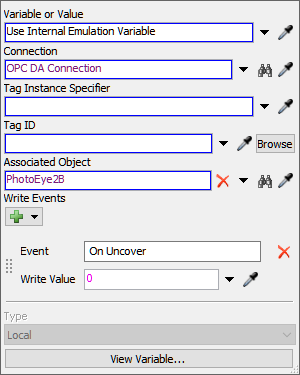
0. - With PhotoEye 1B selected, press Ctrl+C to copy this variable. Click a blank space in the Conveyor 2: Indicate When Area Is Clear shape and then press Ctrl+V to paste the variable into this shape.
- Rename the copied variable Variable: PhotoEye 2B.
- Click Variable: PhotoEye 2B to select it. In Quick
Properties, next to the Associated Object box, click the
Sampler button
to enter sampling mode.
- In the 3D model, click PhotoEye2B (the second photo eye on the red conveyor) to sample it.

Consider saving your simulation model at this point.
Step 5 Create the Area Restriction Logic
In this step, you'll edit the properties to add the area restriction logic for Conveyor 1. The following is an overview of how each activity will function in the Check Area Is Clear shape:
| Activity | Explanation |
|---|---|
| Source: Item at Photo Eye 1A | This is an event-listening activity that will listen to events in the variable that is linked to PhotoEye1A on the first conveyor. You won't change this logic in this step, so just remember that you'll listen for the On Change event, which means that it will listen for any time PhotoEye1A is covered by a flow item. When the photo eye is covered, it will write a value of 1 to the server. The source will listen for any changes on the photo eye variable. When a value of 1 is written to the server, the source will release a token to the next downstream activity. You won't need to make any changes to this activity since you've already set up its logic. |
| Get Variable: PhotoEye 2A State | The Get Variable activity can read information from other variables connected to the server. In this case, you'll get the value of the PhotoEye2A variable and store that value in a label on the token named PhotoEyeState. If the value is 1, that means that PhotoEye2A is covered. If the value is 0, that means that PhotoEye2A is clear. |
| Decide: Is PhotoEye2A Clear? | This activity will use the PhotoEyeState label to decide which connector it should send the current token to. If the value of the PhotoEyeState label is 1, it will mean the value is true and that PhotoEye2A is covered. In other words, the restricted area is not clear. The Decide will send the token to the series of activities that will stop the motor so that the flow item will wait until the area is clear. If the value of the label is 0, the flow item can proceed and the token will be sent to the Sink activity connected to connector 2. |
| Set Variable: Motor to 0 | This activity will set the motor variable to 0, which will stop the conveyor motor in the 3D model. You won't need to make any changes to this activity since you've already set up its logic. |
| Wait for Event: PhotoEye2A Clear | This activity will hold the token until PhotoEye2A changes to 0, meaning it is clear. Once PhotoEye2A changes to 0, it will release the token to the next downstream activity. |
| Set Variable: Motor to 1 | This activity will then set the motor variable back to 1, which will resume running the conveyor. You won't need to make any changes to this activity since you've already set up its logic. |
And the following is an overview of how each activity will function in the Indicate When Area Is Clear shape:
| Activity | Explanation |
|---|---|
| Source: PhotoEye 1B Is Clear | This activity will listen for any time PhotoEye 1B changes, either from clear or to covered. It will release a token when that change occurs. |
| Set Variable: PhotoEye1A to Clear | This activity will set PhotoEye 1A to clear when it receives a token. |
| Sink: Conveyor1 Area Is Clear | This activity will remove the token from the process flow and the flow item will continue along the conveyor. You'll use the default settings for this activity. |
You'll also copy this logic to the second conveyor's activities too.
To make these changes:
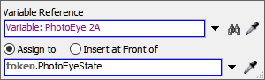
- In the Conveyor 1: Check Area Is Clear shape, click the
Get Variable: PhotoEye 2A State activity to select it. In
Quick Properties next to the Variable Reference box, click
the Sampler button
to enter sampling mode.
- In the Conveyor 2: Check Area Is Clear shape, click the Variable: PhotoEye 2A variable to sample it.
- In the box under the Assign to option, delete the
current text and type
token.PhotoEyeState. - Repeat the previous steps for the Get Variable: PhotoEye 1A
State activity (in the Conveyor 2: Check Area Is
Clear shape), changing its Variable Reference to
Variable: PhotoEye1A. Make sure you change the
Assign to label name to
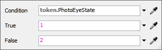
token.PhotoEyeStateas well. - Click the Decide: Is PhotoEye2A Clear? activity to select it. In Quick Properties, click the arrow next to the Send Token To box to open a menu. Select Conditional Decide to open its picklist options.
- In the Condition box, delete the current text and type
token.PhotoEyeState. - Repeat the previous steps for the Decide: Is PhotoEye1A Clear? activity (in the Conveyor 2: Check Area Is Clear shape).
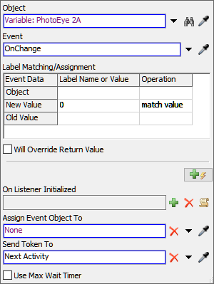
- Click the Wait for Event: PhotoEye2A Clear activity to
select it. In Quick Properties next to the Object box,
click the Sampler button
to enter sampling mode.
- In the Conveyor 2: Check Area Is Clear shape, click the Variable: PhotoEye 2A variable to open a menu. Select Variable: PhotoEye 2A: On Change.
- In Quick Properties, in the Label Assignment / Match Value table, click the cell that is on the New Value row under the Label Name or Value column. Type 0.
- Click the cell that is on the New Value row under the Operation column to open a menu. Select match value.
- Repeat the previous steps for the Wait for Event: PhotoEye1A Clear activity (in the Conveyor 2: Check Area Is Clear shape), but change its Object to Variable: PhotoEye 1A.
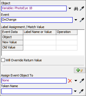
- In the Conveyor 1: Indicate When Area Is Clear shape,
click the Source: PhotoEye 1B Is Clear activity to select
it. Click the Exclamation Point button
 next to this activity to enter
sampling mode.
next to this activity to enter
sampling mode. - Click Variable: PhotoEye 1B to open a menu. Select Variable: PhotoEye 1B: On Change.
- Repeat the previous step for the Source: PhotoEye 2B is Clear activity (in the Conveyor 2: Check Area Is Clear shape), but sample Variable: PhotoEye2B instead.
- In the Conveyor 1: Indicate When Area Is Clear shape,
click the Set Variable: PhotoEye 1A to Clear activity to
select it. Click the Exclamation Point button
next to this activity to enter
sampling mode.
- Click Variable: PhotoEye 1A (in the Conveyor 1: Check Area Is Clear shape) to sample it.
- Repeat the previous steps for the Set Variable: PhotoEye 2A to Clear (in the Conveyor 2: Check Area Is Clear shape), but sample Variable: PhotoEye2A instead.
Reset and run the model:
Notice that when a flow item reaches the first photo eye on Conveyor 2 (the red one), it triggers the stop motor logic and then later resumes the motor when the second photo eye on Conveyor 1 (the blue one) is clear. You could try experimenting with different source arrival times to see how it would affect the queue times.
Conclusion
At this point, you've learned how to emulate basic PLC logic in FlexSim. If you were building an actual manufacturing system, you could program any number of variables for several different PLCs this way and then hand it off to the PLC programmer to program the actual PLC logic that will eventually be used in the system.
Once the PLCs have been programmed, you could possibly use FlexSim to then validate whether the PLCs had been programmed correctly before they are actually implemented in a manufacturing system. To validate this logic, you'd need to connect FlexSim to an actual OPC DA server using the properties in the OPC DA Connection. You'd also have to assign all your emulation variables to their appropriate tag IDs on the server. You'd then change the OPC DA Connection shared asset to "active" in FlexSim so that it will read or write values on the actual server.
At this point you could run the simulation model and test that the PLCs are operating the way they should operate in the actual system. In theory, you would have created a simulation of your future business system in FlexSim. So, the PLC will directly control the elements in the simulation model. You can then observe how the actual PLC has been programmed and compare it to the way the simulation model ran before the PLC was directly connected to the 3D model. See Validating PLC Logic for a deeper explanation.