(Mass) Flow Conveyor
Overview and Key Concepts
The flow conveyor is used to allow continuous flow through the use of multiple input and output ports. The conveyor represents a 'belt' upon which 'dry bulk' can be discharged and transported to the end of the conveyor. The conveyor has a speed that is used to calculate the time required for a product to reach the output of the conveyor. Together with the width of the conveyor the speed also determines the height of the product on the conveyor, based on the input rate. At the output point the outflow rate is a resultant of the speed of the conveyor and the height of the product.

FloWorks provides two conveyor objects: a flow conveyor and a mass flow conveyor. The former is non-accumulating. This means that when the actual output rate of the conveyor is less than the rate that is desired based on the speed and product height, the conveyor will stop. You should then take a manual action, such as
- increase the downstream capacity, for example by changing the receiving object's maximum inflow rate;
- decrease the desired outflow rate by lowering the speed of the conveyor, such that the same amount of material will flow out in less time;
- discard the overflow by attaching a sink of infinite capacity as the last ranked output port.
After taking one of these measures, you need to restart the conveyor by calling the resume method.
By contrast, the mass flow conveyor is accumulating. When the actual output rate is lower than the requested output rate, the material that cannot exit will stack up against the output end of the conveyor up to a predefined maximum height. Compared to the non-accumulating conveyor, the mass flow conveyor has some restrictions which are described in more detail below.
For the regular conveyor, inputs may be placed anywhere along the length of the conveyor. Each input location is visualized by an arrow, which is colored according to the product entering through that port, and optionally a little square blocking the arrow to indicate that the input is closed. Products from different input ports will stack on top of each other and as long as this material is in transport the conveyor you can visually track these layers. Upon reaching the end of the conveyor, this information is lost - it is assumed that since the products are stacked only the topmost product will be visible outside the conveyor. The output point of the conveyor is always at one of the ends of the conveyor - usually the farthest point along the conveyor, unless the conveyor's direction has been changed.
For the mass flow conveyor, it is not possible to have inputs enter at other points than the start of the conveyor. Also the mass flow conveyor does not keep track of different layers,
in case the input objects have different input types. The product on the mass flow conveyor will be visualized as being of the product type of the
The non-accumulating conveyor has a maximum capacity. The conveyor will stop() whenever the flow at any point along the conveyor exceeds the capacity. In contrast, the mass
flow conveyor has a similar property called maximum density, which determines the maximum height (volume per unit of surface area) of product anywhere along the conveyor. This includes any
flow "backing up" from the end of the conveyor due to restrictions in output rate.
Events
The flow conveyor uses the standard events that are common to almost all FloWorks objects. See FloWorks Triggers for an explanation of these events.
The flow conveyor has the following additional events:
On Product Change
This event occurs whenever the product leaving the pipe changes. This event is commonly used to switch output ports or take some other action based on the new product type. The provided dropdown options include an option to pass the new product downstream - this will set the product of a specified output object to the new type. You can use this to link multiple conveyors or pipes and conveyors together and automatically create a multi-product pipeline based on the actual output product of the first conveyor.
It has the following parameters:
| Event Parameter | Explanation |
|---|---|
| curproducttype | The product ID or name of the product type that was leaving prior to this event. |
| newproducttype | The product ID or name of the product type that will be leaving after this event. |
States
For statistical purposes, the conveyor's FloWorks state profile will be in one of the following states at various points during a simulation run:
- Empty - The conveyor is empty and there is no flow.
- Filling - The conveyor's inflow rate exceeds the outflow rate.
- Releasing - The conveyor's outflow rate exceeds the inflow rate.
- Not empty - The conveyor is not empty but there is no net flow because the input rate is equal to the output rate.
- Idle - The conveyor has stopped because the requested output rate exceeds the downstream capacity.
Properties
The flow conveyor has five tabs with various properties, the mass flow conveyor has six. These are the FloWorks / flow conveyor specific tabs:
- The Settings Tab
- The Flow Tab
- The Level Indicator Tab, for the mass flow conveyor only.
- The Triggers Tab
The last two tabs are the standard tabs that are common to all fixed resources. For more information about the properties on these tabs, see:
Settings
Control, flow arrows
These settings are described here.
Draw (dis)charge indicators
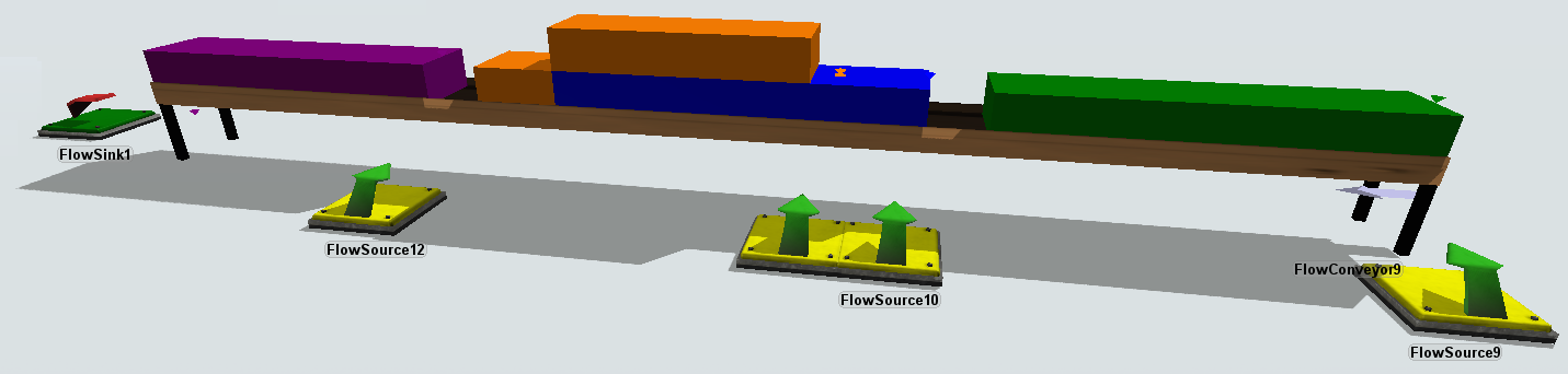
When this option is enabled, small conical arrows will be drawn over the input points of the conveyor and below the output point of the conveyor. The color of the input arrows indicates the product entering at that point. If more than one product is entering at the same point, the input indicator will have the color of the last entering product (the port with the highest port number) as this will be the product at the top of the stack. In addition, if the flow rate of a port is zero, a small square will be drawn under the conical arrow, "blocking" the input from entering. In the example below, there are two inputs: green product is entering at the start of the conveyor. There is another input connected at 1 m from the start of the conveyor which will provide blue product, but it is currently blocked (in this case, output of the source was closed). Similarly the output indicator drawn below the output point at the end of the conveyor indicates, by its color, the product that is flowing out of the conveyor; a square "blocking" it from below means that no output is currently taking place.
Conveyor speed
The speed of the conveyor determines how fast products will reach the end, but also how tall they will be on the conveyor. The actual size of the conveyor is used, so an inflow of 100 per time unit on a conveyor of 20 length units wide will be 5 length units tall.
Scale factor
Scales the height of the conveyor contents (not the actual conveyor object). In the example given under "conveyor speed": if you would set the scale factor to 0.2, the product on the conveyor would only be drawn 5 × 0.2 = 1 length unit tall. This may be useful if you have flows that would otherwise be so small that you cannot see any differences in height or which products are stacked; or when the speed is so low and volume so high that there would be an unrealistically tall "wall" of product running over the conveyor.
Max inflow capacity (flow conveyor only)
This option determines the maximum capacity at any point along the conveyor. The value is given as a flow rate. The conveyor will be automatically stopped if this value is exceeded at any point on the conveyor by the inflow from external sources at that point combined with the flow already present on the conveyor.
Maximum density (mass flow conveyor only)
For the mass flow conveyor, this setting determines how tall product may "stack up" against the end of the conveyor before it starts "crawling back" towards the start. By taking into account the width of the conveyor, the maximum density can be converted into a maximum product height and vice versa. The image below shows how having a relatively small maximum density will make the conveyor fill up relatively quickly.
Ground length
This is the length of the conveyor as measured along the ground. Currently FloWorks conveyors do not support multiple sections.
Conveyor rise
This is how many length units the conveyor rises along its complete length; in other words, what the height difference is between the start and end of the conveyor.
Belt length
This is an automatically calculated field, that shows you what the actual conveyor belt length would be based on the ground length and conveyor rise. According to the Pythagorean theorem, the belt length is given by B2 = L2 + h2, where B is the belt length, L is the ground length and h is the rise.
Flow
The Flow tab of the conveyors is slightly different from the Flow tabs of most other FloWorks objects, as you cannot set the flow rates of the conveyor directly.
Input
For the flow conveyor, the Input section shows a table of all the connected input objects. For each input object, enter a length, measured along the conveyor belt, at which the input object will enter. For the mass flow conveyor, this option is not available: all material has to enter at the start of the conveyor.
Max. outflow rate
The maximum outflow rate field shows the current maximum outflow rate as determined by the conveyor. The conveyor will set this value to the rate required to precisely release all material currently reaching the end of the belt. If you restrict this flow downstream, the conveyor will stop (in the case of a flow conveyor) or start accumulating towards the beginning of the belt (for the mass flow conveyor).
Outflow rule
You can specify the outflow rule - send flow through the ports in connection rank order, or maintain a fixed ratio between all outflow ports. Notice that the latter may lead to unintended reductions in overall outflow rate, that may in turn stop the conveyor.
Level indicator (mass flow conveyor only)
The Level Indicator tab has the following properties:
Draw Level Indicator
If this is checked, the level indicator bar will be drawn on the object.
Rectangular
If this is selected, the level indicator bar will be drawn as a colored box.
Cylindrical
If this is selected, the level indicator bar will be drawn as a colored cylinder.
Position, Rotation, and Size
Here you can set the position, rotation, and size of the bar based on X, Y, and Z values.
| Field | Description |
|---|---|
 |
Change the position of the object. |
 |
Change the rotation of the object. |
 |
Change the size of the object. |
Custom coding
You may control the behavior of the conveyor dynamically by writing FlexScript, for example in a Script window or by changing the code behind one of the options in an object trigger.
The conveyor is an instance of the FlowObject class, see the class reference
for information about its properties.
When the flow conveyor blocks because the actual output rate is too low, call Object.resume() to restart it.