Task 4.2 - AGVs Using Process Flow
Task Overview
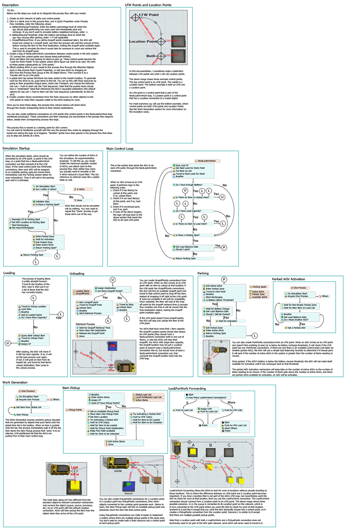
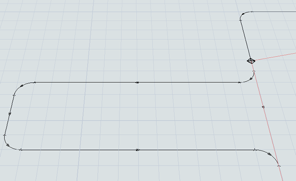
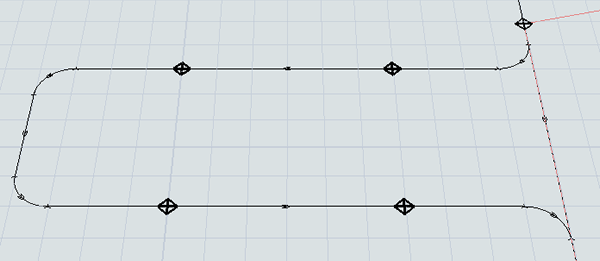
To make AGV simulation even simpler, FlexSim has two pre-built AGV process flow templates you can use with your AGV simulation project. These process flow templates already have the basic logic needed for most AGV systems. The following image shows a zoomed out version of the AGV template:
In this tutorial task, you'll learn how to set up the process flow template. You'll also learn how to create pick up areas, drop off areas, and park points. At the end of the tutorial, you'll learn how to adjust control point sensitivity in order to make your system more efficient.
While it is beyond the scope of this tutorial to explain the exact details of how the AGV template works, you should be aware that this process flow will control nearly all of the logic in this AGV system. Consider exploring the AGV process flow template in more detail to learn how it works. The template is organized by function and is self-documented to help you understand it.
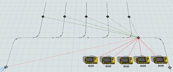
When you're finished, your model will look similar to the following image:
Step 1 Add the AGV Process Flow Template
In this step, you'll create the AGV Process Flow template and attach the AGVs to the process flow. As you'll see in this step, the basic set up is fairly simple. After creating the process flow template, you'll need to attach the AGVs to the process flow. Then, you'll set the processors to push transportation tasks to a global list called AGVWork, which is automatically created when you set up the AGV process flow. Once the AGVs are attached to the process flow, you won't need the dispatcher object, so you can delete it.
In order for the process flow to work correctly, you'll also need to create a Next Look For Work loop. A Next Work For Work loop is basically a series of control points that are connected to each other in a loop. Once this circuit has been set up, the AGVs in the system will loop continuously through the network looking for transportation tasks to work on. You'll set up the Next Look For Work system in the main AGV network in this step.
To add the process flow and set up its logic:
- On the main toolbar, click the Process Flow button to open a menu. Point to Add a Task Executer Process Flow and then select AGV to create this process flow template.
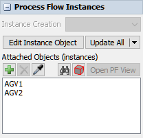
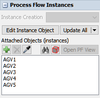
- In the newly created process flow, click a blank area to ensure nothing is selected.
In Quick Properties under the Process Flow Instances group,
find the Attached Objects (instances) box. Click the
Sampler button
 by this box to enter sampling
mode.
by this box to enter sampling
mode. - In the 3D model, click AGV1. It should now show up in the Attached Objects box.
- Repeat the previous steps to attach AGV2 to the process flow as well.
- Now that the AGVs are attached to the process flow, you can delete the AGVDispatcher in the 3D model.
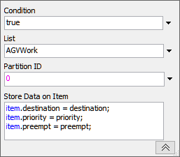
- In the 3D model, double-click the Staging1 processor to open its properties window. On the Flow tab, click the arrow next to the Use Transport box to open a menu. Point to Use List, then select Push to Item List (no task sequence) to open a picklist window.
- Check that the List box shows that the AGVWork list is currently selected. Leave the rest of the properties on their default settings.
- Click the OK button to save the changes and close the properties window.
- Repeat the previous steps to add the AGVWork list to the Staging2 processor as well.
- If the two AGVs are currently hovering over the AGVEntryPoint control point, drag those away from the control point so the control point is visible.
- Create a connection (A-connect) from the AGVEntryPoint control point to the MainDropOffPoint control point to open a menu. Select NextLookForWork. A red line will appear showing the two control points are connected.
- Repeat the process to create Next Look For Work connections looping between the rest
of the control points in the following order:
- From the MainDropOffPoint control point to the MainPickUpPoint control point
- From the MainPickUpPoint control point to the bottom left control point
- From the bottom left control point to the bottom right control point
- From the bottom right control point to the lower right control point
- From the lower right control point to the upper right control point
- From the upper right control point to the AGVEntryPoint control point
Reset and run the simulation model:
If you'll recall from the end of the previous tutorial task, there was a problem in which AGV1 and AGV2 get deadlocked. Fortunately, this problem no longer occurs because both AGVs now loop around the system continuously looking for work, regardless of whether there is actual work that needs to be performed or not. The AGV process flow template automatically creates this logic.
Step 2 Add a Pick Up Area
In this step, you'll learn how to add a pickup area and connect pick up control points to location control points. You'll create pickup stations where up to 10 items can wait for transportation by an AGV.
When you're finished with this step, your 3D model will look similar to the following image:
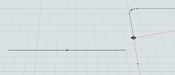
To create a pick up area:
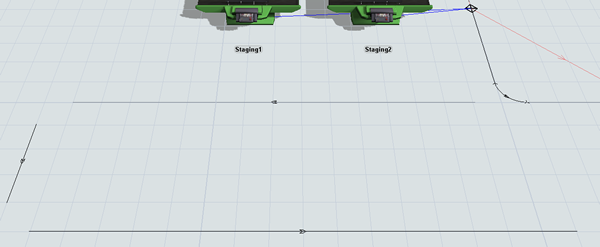
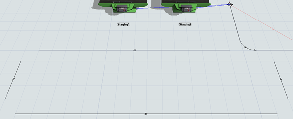
- Create a horizontal AGV path going from right to left extending out from the lower left corner of the AGV network that is 16 units long. Leave 1 unit of space on either end.
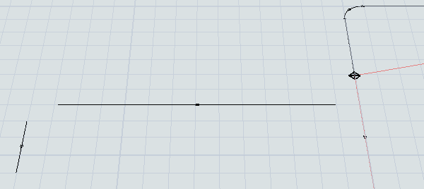
- Create a vertical AGV path going from up to down that is 3 units long. The path should be 1 unit left and down from the previous path.
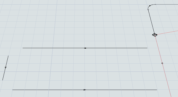
- Create a horizontal path going from left to right that is 18 units long. It should be 1 unit right and down from the previous path.
- Create a vertical path going down to up that is 3 units long. It should be 1 unit right and up from the previous path.
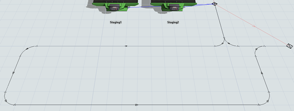
- Use the Join Paths tool in the Library to join these paths together. Join the main AGV path to the first and last new path you created. Make sure the join paths flow in the same direction as the other paths.
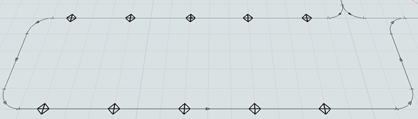
- Add 10 control points to the top and bottom paths, spacing them about 3 units apart.
- For clarity, rename the new control points as PickUp1, Pickup2, etc. in the order that the AGVs will pass over them.
- Create a control point connection (A-connect) from MainPickUpPoint control point to the PickUp1 control point to open a menu. Select PickUpPoints. A green line will appear showing the two control points are connected.
- Repeat the previous steps to create pick up control points from the MainPickUpPoint to all 10 of the pick up control points.
- Open the DeliverySchedule process flow.
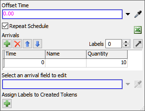
- Click the Source: MedSupplies Deliveries activity to
select it. In Quick Properties, under the Arrivals group,
find the cell on the first row under the Quantity column.
Type
10in this cell.
Reset and run the model:
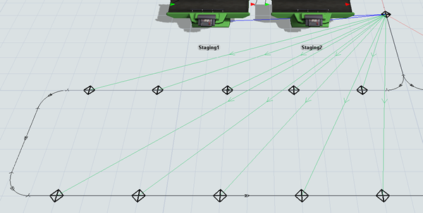
Notice that the flow items enter the queue and the processors begin processing them. Then, the processors pass them to the MainPickUpPoint control point, which immediately diverts the items to one of the ten pick up points. When the AGVs pass over the MainPickUpPoint looking for work, it diverts them to the pick up area. The AGVs then load the flow items and transport them to their destination.
If you keep the model running long enough, the AGVs will transport all of the items. Notice that when that happens, they will bypass entering the pick up area because there isn't any transportation work in that area for them to work on:
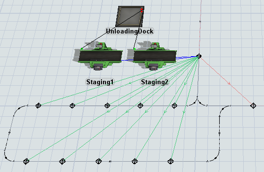
Step 3 Add a Drop Off Area
In the same way that you can create pick up points for AGV transfers, you can also create drop off points for fixed resources. This step will guide you through the process.
When you're finished with this step, your 3D model will look similar to the following image:
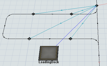
To create a drop off area and use a global list:
- In the 3D model, delete the DropOff sink.
- Create a horizontal AGV path going from right to left extending out from the upper left corner of the AGV network that is 12 units long. Leave 1 unit of space on either end.
- Create a vertical AGV path going from up to down that is 3 units long. The path should be 1 unit left and down from the previous path.
- Create an identical horizontal path going from left to right that is 12 units long. It should be 1 unit right and down from the previous path.
- Use the Join Paths tool in the Library to join these paths together. Join the main AGV path to the first and last new path you created. Make sure the join paths flow in the same direction as the other paths.
- Add 4 control points to the top and bottom path, spacing them equally along the path.
- For clarity, rename the new control points as DropOff1, DropOff2, etc. in the order that the AGVs will pass over them.
- From the Library, add a Queue to this area.
- For clarity, rename the new queue LoadingDock.
- Create a connection (A-connect) from the LoadingDock queue to the MainDropOffPoint control point.
- Create a connection (A-connect) from the MainDropOffPoint control point to the DropOff1 control point to open a menu. Select DropoffPoints. A light blue line will appear to show that the location control point is now connected to the drop off control point.
- Repeat the previous steps as needed to create additional drop off control points for the other three drop off control points.
Check that your simulation model looks similar to the image shown at the beginning of this step.
Step 4 Use Lists to Set Item Destinations
In this step, you'll learn about a different method to send items to a downstream object. Rather than using port connections, you'll push and pull items from a global item list named ItemsReadyForDelivery. You'll also change the Dropoff sink to a queue instead.
Although lists require a little more thought to set up correctly, lists are sometimes better for item routing in an AGV model because they don't require making port connections over potentially long distances. Lists can also simplify what many-to-many port routings for models with many different origin points and many different destination points.
To create a global item list:
- In the Toolbox, click the Add button
 to open a menu. Point to
Global List, then select Item
List.
to open a menu. Point to
Global List, then select Item
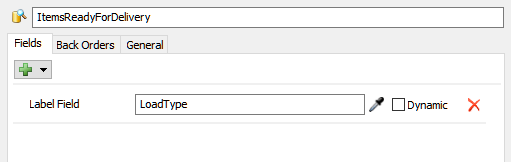
List. - In the list properties window, change the list name to ItemsReadyForDelivery.
- In the Label Field box, delete the current text and
type
LoadType. - Delete all the Expression Fields.
- Press the OK button to save the changes and close the window.
- Double-click the Staging1 processor to open its properties window. In the Flow tab, click the arrow next to the Send to Port button to open a menu. Point to Use List, then select Push to Item List.
- Click the arrow next to the List box to open a menu. Select ItemsReadyForDelivery.
- Click the OK button to save the changes and close the window.
- Repeat the previous steps for the Staging2 processor as well.
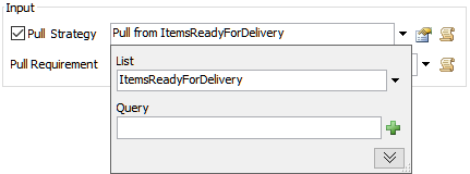
- Double-click the LoadingDock queue to open its properties window. In the Flow tab in the Input group, check the Pull check box.
- Click the arrow next to this box to open a menu. Point to Use List and select Pull from Item List.
- Click the arrow next to the List box to open a menu. Select ItemsReadyForDelivery.
- Click the OK button to save the changes and close the window.
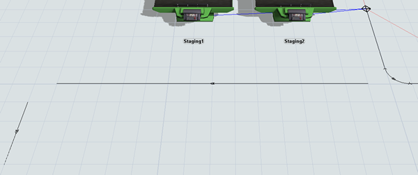
![]()
Reset and run the model:
Notice that the first AGV drops off at DropOff4 and the second AGV drops off at DropOff3.
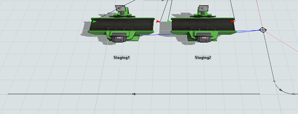
Step 5 Add Park Points
In this step, you'll add three more AGVs to the model for a total of five. You'll also create park points for each of the AGVs. Park points are locations where AGVs begin when the simulation model first starts running. During a simulation run, an AGV can return to the park point to recharge its batteries when they are running low.
When you're finished with this step, your 3D model will look similar to the following image:
To add additional AGVs and create park points:
- From the Library add three more TaskExecuter objects to the 3D model.
- For clarity, rename these AGVs as AGV3, AGV4, and AGV5.
- Open the AGV process flow.
- Click a blank area to ensure nothing is selected. In Quick Properties under the
Process Flow Instances group, find the
Attached Objects (instances) box. Click the
Sampler button
by this box to enter sampling
mode.
- In the 3D model, click AGV3. It should now show up in the Attached Objects box.
- Repeat the previous steps to attach the other two new AGVs to the process flow as well.
- Drag AGV1 and AGV2 away from the AGVEntryPoint control point so that it is visible in the 3D model.
- Create a port connection (A-connect) from AGV2 to the AGVEntryPoint control point to open a menu. Select Traveler AGV. A red line will appear showing the second AGV is connected.
- Repeat the previous step to connect the rest of the AGVs to the control point.
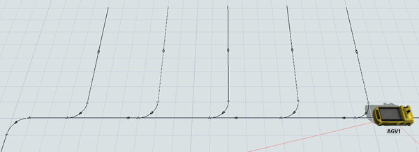
- In the top left corner about 4 units away from the corner, create a vertical AGV path that is 6 units.
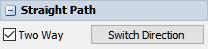
- Click the new path to select it. In Quick Properties, check the Two Way check box.
- Press Ctrl+C to copy the selected path. Press Ctrl+V to paste a copy of the path in the model.
- Repeat the previous step to create 5 paths. Space the paths out so that they are about four units apart from each other.
- Use the Join Paths tool in the Library to join each park path to the main AGV network.
- Click one of the new joining paths you created to select it. In Quick Properties, check the Two Way check box.
- Repeat the previous step to change all the new joining paths to two-way paths.
- From the library, add a Control Point to the middle of one of the park paths.
- Repeat this step for all five park paths.
- For clarity, rename these new control points ParkPoint1, ParkPoint2, etc.
- Create a port connection (A-connect) from the AGVEntryPoint control point to the ParkPoint1 control point to open a menu. Select ParkPoints. A dark green line will appear showing the second AGV is connected.
- Repeat the previous steps to connect the AGVEntryPoint control point to the rest of the park points.
Reset and run the simulation model:
When the simulation starts, all five AGVs start in their designated park points and then travel throughout the network working on the transportation tasks. You'll notice that sometimes the AGVs have to stop momentarily. You'll learn how to reduce the amount of time an AGV waits at a control point in the next step.
If you keep the model running long enough, the AGVs will transport all of the items. Notice that when that happens, the AGVs will eventually all return to their park points to charge their batteries instead of idly looping around the system:
Step 6 Change Control Point Sensitivity
In the previous step, you noticed that sometimes the AGVs had to stop while waiting for the AGV on the path ahead of them to clear the control point its on. That's because AGV networks have a sophisticated look-ahead mechanism that can avoid crashes by determining if the next control point on the path is available or not. If it is not available, the AGV will wait at its current control point.
By default, the control points don't become free until the AGV that claimed it has reached the next control point. You can change the control point's sensitivity so that the AGV merely has to clear the control point itself before the control point can be allocated by another AGV. You'll learn how to change this sensitivity by changing its Deallocation Type property in this step.
To change the AGV system's control point sensitivity:
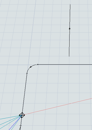
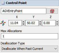
- Drag the five AGVs away from the AGVEntryPoint control point so that it is visible in the 3D model.
- Click the AGVEntryPoint control point to select it. In Quick Properties, click the Deallocation Type menu to open it. Select Deallocate When Past Current.
- Repeat the previous step for all the control points on the main AGV network.
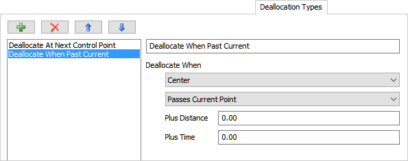
- In the Toolbox, double-click the AGV Network to open the network properties window.
- On the Deallocation Types tab, select Deallocate When Past Current from the type menu.
- Under the Deallocate When heading, click the first menu to open it. Select Center.
- Press the OK button to save the changes and close the window.
Reset and run the simulation model:
Notice now that the AGVs are more efficient as they travel through the system. The AGVs deadlocks less often and they quickly space themselves out efficiently throughout the network.
Conclusion
Now you've learned how the AGV process flow template makes it possible to do even more complicated AGV behavior like pick up points, drop off points, and park points. You've also learned how to adjust control point sensitivity to make your system more efficient if needed. In the next tutorial, you'll learn how to add elevators to your AGV system so that AGVs can travel to multiple floors if needed. Continue on to Tutorial 4.3 - Using Elevators With AGVs.