Task 3.2 - Multi-compartment loading
Task Overview
In this task you will learn about the Berth and Loading Arm object in FloWorks. The Berth is not a flow object, but a Fixed Resource that can also be used outside of a fluid or bulk context to model vessels loading or unloading. The Loading Arm forms the link between the Berth and the fluid objects: instead of giving the berth a fixed processing time, it allows the (un)loading process to be determined by the capacity and flow rates of the vessel and the onshore flow origin (such as a tank, stock pile, mixer or even a flow source) or destination.
Step 1 The second product
To support loading of a secondary product, you will first have to duplicate the infrastructure for a single product you have created in the previous task. Select all the flow source, flow pile, loading arm and – if you have added it – deferred production sink at the production site, by holding down Control and clicking the objects. Making sure you have not selected the berth or port queue, copy the objects and set their product type to 2 (only the product type of the stock pile is relevant).
Do the same at the consumption side.
Step 2 Adding a tank to the vessels
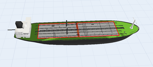
You'll need to add an additional tank to the flow vessels, which they can use to transport the secondary product. In the Toolbox, find the FlowItem Bin, then double click the Flow Vessel.
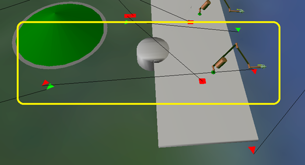
Click the tank on the vessel (watch the yellow box to make sure you select the tank, not the vessel) and press Control + C to copy it. Then click on the vessel and press Control + V to paste the tank as a component (subnode) of the vessel. By default the tank will be shown floating above the vessel, but if you copied it correctly you can move the vessel around and see both tanks move with it.
When you run the model as is, you will now see the flow vessels only being filled for 50%, with green product.
Step 3 Multi-compartment loading controller
Each berth now should have two loading arms, each connected to one of the two flow piles. Theoretically, each of the tanks can have different loading times because of the flow rate constraints on all involved objects and the available stock in the stock piles. Therefore, we can no longer rely on a single loading arm to tell the berth when the vessel is allowed to leave. Instead, we'll use a Multi-Compartment Loading Controller to coordinate the berths, in a way somewhat resembling the Dispatcher for operators.
At the production site, add a Multi-Compartment Loading Controller (MCLC) from the FloWorks drag-drop library. Disconnect the loading arm(s) from the berth (‘W’-drag). Then create center connections (‘S’)...
- ... between the berth and the MCLC
- ... between the two loading arms and the MCLC
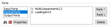
The center ports of the MCLC should then look as shown below:
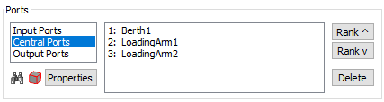
Open the properties of the MCLC. On the first tab, you can define the loading steps. All the loading arms attached to a single step are allowed to load or unload simultaneously. Only when all loading arms in a step report that they are done loading, the loading will continue to the next step. In this case you'll only need a single step that allows both loading arms to load at the same time. This is already the default, so you don't have to change anything here.
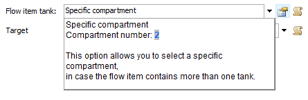
The only thing that you still have to do, is tell the second loading arm to load the second compartment, as the
default is to always load the first (only) compartment. Double click the second loading arm. In the
“Flow item tank” field, change the default “Tank on flow item” to
“Specific compartment”. In the settings popup, enter 2 as the compartment number.
This will make the loading arm connect to the second object inside the flow item.
Do the same on the other side: add a MCLC, and center-connect it to the berth and the two loading arms.
Make sure both loading arms are set to unload mode and that the second loading arm unloads the second compartment.
Set the unloading rate of one of the loading arms to 12, so you can verify that the MCLC actually waits for both
compartments to finish unloading before the vessel is released.
Step 4 Third party vessels
Back in Task 3.1 (step 3), we noted that a
loading arm is either in loading or in unloading mode, and promised that we would show how to use a single berth
to both load and unload a vessel. Suppose that in addition to our own fixed fleet of vessels, we have an
interweaved arrival pattern of third party vessels that will only deliver the green product (1),
with an inter-arrival time of 200.
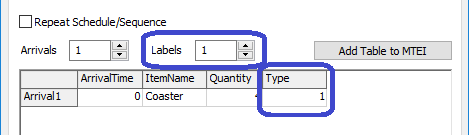
First you’ll need a way to distinguish between your own vessels and the third party vessels. Double click
on the vessel source in the model, and set the number of Labels to 1. Name the extra column that appears
in the arrival table “Type” and give the vessel an item type of 1.
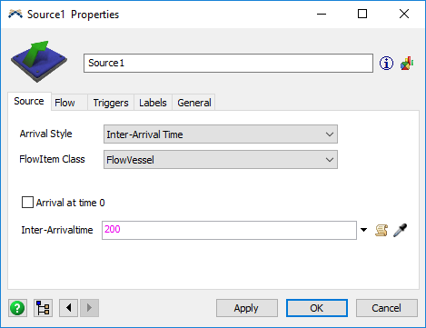
At the consumption site, add another (flow item) source, and connect it to the port queue.
Set its FlowItem Class to FlowVessel, with an inter-arrival time of 200.
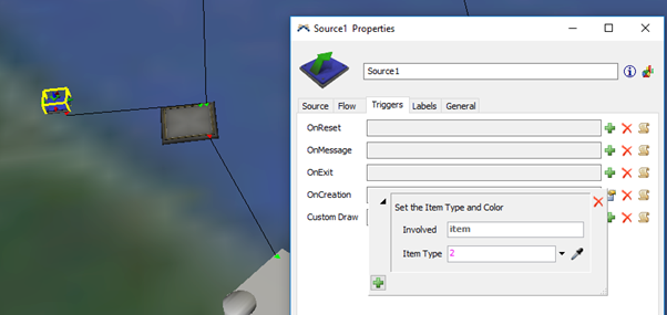
You'll need to add an On Creation trigger. Use the Set Item Type and Color option from the
Data submenu to set the item type to 2.
At the berth, you’ll need to add a loading arm for loading the vessel. Add a loading arm, connect the green stock pile to it, and center connect it to the berth.
Set the maximum flow rate of the loading arm to 3. The berth should now have
two center connections: the first one to the unloading (multi-compartment) controller,
the second one to the loading arm.
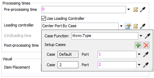
You can now tell the berth to use the first loading controller for vessels of type 1 (your fleet),
and the second loading controller for vessels of type 2 (third party). One way to do this, is to
select the “Center Port By Case” option for the loading controller, and using item.Type
as the case function. Select center port 2 for item type 2, and center port 1 for all other types:
When you run the model, you should now see that your own vessels unload both of their compartments through the MCLC, while the vessels generated by the source load the green compartment through the other loading arm, then leave.
The only remaining problem with the model is, that the third party vessels will also return to the production site and clog up the queue there. To solve this, connect the berth at the consumption side to a (flow item) sink, so that its first output port goes to the production site port queue and the second output port goes to the sink at the consumption side.
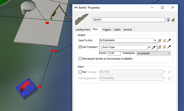
In the “Send to port” expression of the berth (in the Quick Properties or on the Flow tab of the
properties window) select “By Expression” and use the default of item.Type. This will send
vessels of type 1 (own fleet) through output port 1, so the production site, and the third-party vessels of type
2 to the sink through port 2.
When you run the model now, you will regularly see a loading vessel interfere with the pattern of the unloading vessels, blocking the berth and reducing the green stockpile. Consider it an exercise to add a second third-party type which only loads the blue product, or if you are up for a challenge, perhaps randomly select one of the two compartments to fill.
Conclusion
This task concludes the FloWorks Loading Points and Berths tutorial.