Tank visualization
Tank shapes
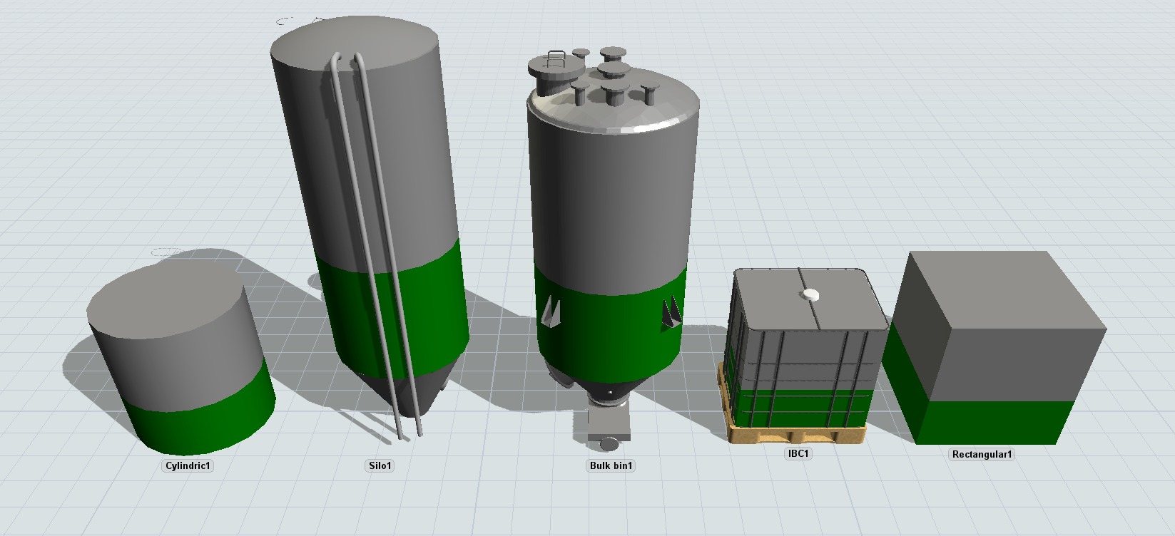
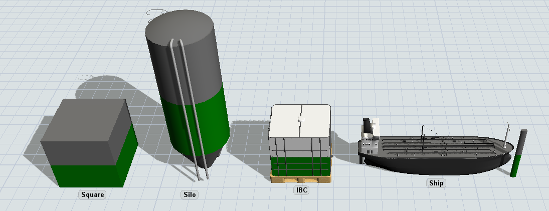
By default the flow tank is modelled as a cylindrical or rectangular container, depending on the shape of the level indicator. FloWorks provides a few additional visualizations on top of this base shape, such as a silo, bulk bin or intermediate bulk container (IBC). These shapes can be selected when adding a tank to the model by clicking instead of dragging the Flow Tank object in the Library, or set on an existing tank using the Shape panel in the properties window.

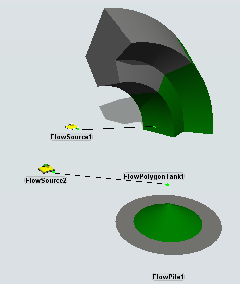
In some cases you may want to model the geometry of a real-life situation in more detail. For example, you may be releasing bulk material onto a pile which settles into a conical shape. Or you may be filling a specific shape with a polygon surface area, in coastal protection construction. FloWorks provides two specific versions of the flow tank, which are functionally identical to the regular flow tank but provide a different in the geometry. Therefore their Settings Tab will vary slightly. This applies to the "pile" and "polygon" shapes. You can select these options just like the other shapes mentioned above, but instead of using a standard cylindrical or rectangular level indicator, they will use special internal logic to draw their contents, to provide a more realistic visualization.

The level indicator
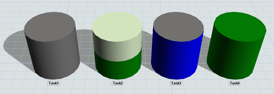
All content-holding objects, such as tanks and mixers, have a system for displaying the current content of the objects as a percentage of the maximum content. This system colored bar is called the level display or level indicator. The Tank and Mixer have no 3D shape by default and only use this bar to visualize the object. The bar consists of two layers. The bottom layer represents the current content of the object using the color of the product it contains. The top layer uses the object's color (usually, dark gray) to represent the amount of empty space left in the object. If a bar is displayed as fully gray, that object is empty. If a bar is fully colored, including the top cap, that object has reached its full capacity.

The level indicator bar can be moved, resized and rotated for each object in the model. The modeller can also state whether the bar is rectangular or cylindrical. The size of the bar is measured as a percentage (0 - 1) of the size of the object. The location is relative to the size of the object as well. The point (0,0,0) is one corner of the object's bounding box while (1,1,1) is the opposite corner. This flexibility allows the modeller to position the level indicator bar in such a way that it appears to be part of the object's 3D shape.
