Overview of the FlexSim User Interface
Introduction
This topic will provide a high-level overview of the most important elements of the FlexSim user interface and will explain some of its key terms and concepts.
You will primarily build your simulation model using two interfaces: the 3D model and the Process Flow tool. The 3D model is where you will visualize your business system using 3D graphics. The Process Flow tool is where you will build the logic that powers your 3D model.
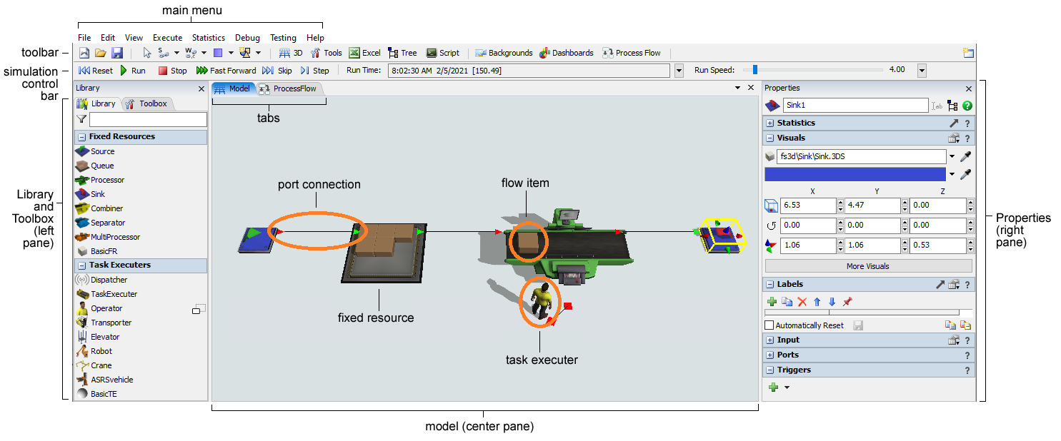
The most important elements of the 3D model interface are labeled in the following image:
The Process Flow interface closely resembles the 3D model interface. The most important elements of the Process Flow tool are labeled in the following image:
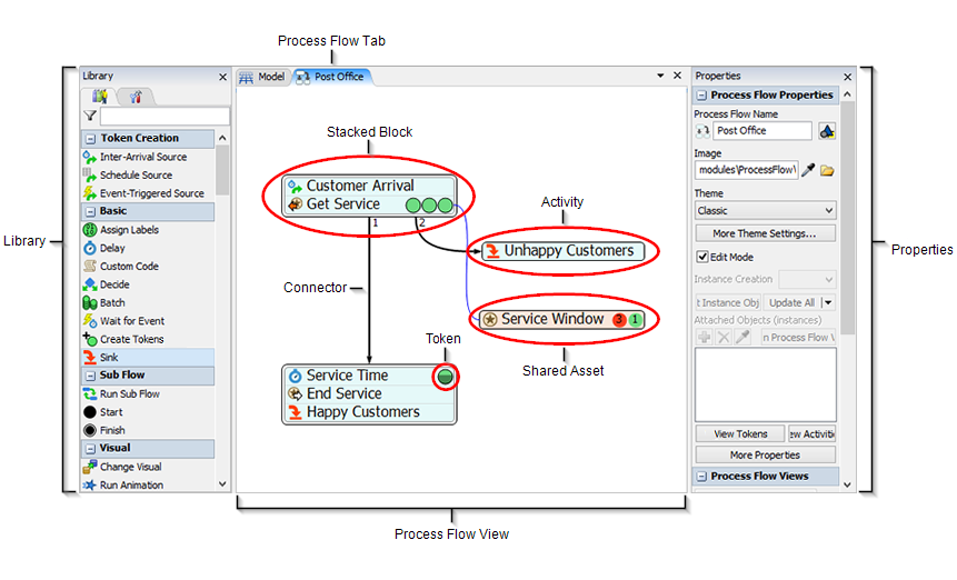
This topic will focus on explaining the elements of the 3D model interface. To learn more about the Process Flow interface, see Overview of the Process Flow Interface.
3D Model (Center Pane)
Located in the center pane, the 3D model is the main workspace you will use to create a 3D simulation model of your business system. You can drag objects from the Library into the model to begin creating your simulation. When you run a simulation, the objects in your simulation model will begin to move and interact based on the logic you've defined in your simulation model.
Objects (Fixed Resources, Task Executers, Flow Items)
Objects are the basic building blocks of a 3D simulation model. Different types of objects have different purposes and functions within the simulation model. Some of the most common objects are:
- Flow items - Objects that move (or "flow") through the simulation model, usually from one station (typically a fixed resource) to another downstream station. Flow items can represent products, customers, paperwork, parts, or any other item that moves to various stations in your business system. By default, flow items look like boxes, but you can change the flow items to look like people (customers) or other shapes.
- Fixed resources - Objects that remain stationary in the 3D model. Each fixed resource performs a specific function. For example, a source creates flow items at specific intervals and introduces them to the model. A queue stores flow items until they are needed downstream. A sink removes flow items from the model, and so forth.
- Task executers - Objects that can move around in the 3D model and perform tasks such as transporting flow items, operating machines, etc. The most common type of task executer is the operator, which can represent an employee in the simulation model.
There are many types of objects besides the main ones mentioned here. See Types of 3D Objects for a more thorough explanation.
Library and Toolbox (Left Pane)
Located in the left pane, the Library contains a variety of objects that you can use to build your 3D simulation model. Each type of object has specific settings (properties) that you can customize. (See Overview of 3D Library Objects for more information about these objects and their properties.) Sometimes the Library will display different objects based on the tool that is open and active in the center pane at the time. For example, when the Process Flow tool is open, the Library will display a set of objects (activities) that are unique to Process Flow.
The Library also shares the left pane with the Toolbox, which is where you will manage the tools you want to use in your simulation model (such as Process Flow, Dashboards, Global Tables, etc.). See Using the Toolbox for more information.
Properties (Right Pane)
Located in the right pane, Properties allows you to edit the properties for any object that is currently selected in the model or in a given tool. You can also use the Properties pane to view important information (such as statistics) about objects when they are selected during a simulation run. See Using the Properties Pane for more information.
Tabs
When you open some of the tools in FlexSim, they might split or share the center pane with the simulation model. These tools each have their own tab in the center pane. You can click the tabs to make them active if needed. You can also control how FlexSim displays these tools or how they split the center pane. See Arranging Windows and Tabs for more information.
Ports and Port Connections
Objects in the simulation model need to be connected in some way in order to interact during a simulation model. One of the ways in which objects can be connected is through ports. There are two types of ports in FlexSim:
- Input/Output ports - These ports determine how and when a flow item passes from one fixed resource to another. When an output port on one fixed resource is connected to the input port of another object downstream, the flow item will pass from the first object's output port to the next object's input port (unless that port is closed).
- Center ports - When the center ports of two objects are connected, it creates a reference point between those two objects. Center ports allow objects to communicate or interact. Center ports most typically connect a fixed resource to a task executer.
Main Menu, Toolbar, Simulation Control Bar
As in most software programs, the main menu contains all of the tools and commands you might use while building your simulation model.
The toolbar gives quick access to many of the commonly used tools and commands in FlexSim.
The simulation control bar (also sometimes called the control bar for short) contains the tools and commands you will need to run your simulation. See Running Simulations for more information about how to use the simulation control bar.
Environments
Located in the top right corner, the Environments button  lists available environments. Environments customize the look and feel of the program to better serve the
needs of different kinds of users. For example, the Healthcare environment customizes the toolbar and reorders
the library so that healthcare related tools and objects are more prominently displayed.
lists available environments. Environments customize the look and feel of the program to better serve the
needs of different kinds of users. For example, the Healthcare environment customizes the toolbar and reorders
the library so that healthcare related tools and objects are more prominently displayed.