Moving, Resizing, and Rotating 3D Objects
Introduction to Moving, Resizing, and Rotating 3D Objects
FlexSim uses the classic Cartesian coordinate system to position objects within the model. For that reason, FlexSim uses the terms X, Y, and Z to refer to the axis coordinates for the position, rotation and size of the object:
- The X axis moves the object from left to right, resizes the object's length, and rotates the object using the X-axis as its center point
- The Y axis moves the object forward and back, resizes the object's width, and rotates the object using the Y-axis as its center point
- The Z axis moves the object up and down, resizes the object's height, and rotates the object using the Z-axis as its center point
You can use either your mouse or the tools in the Visuals panel of Properties to move, rotate, and resize the objects in your model. This section of the guide will discuss both methods.
Moving 3D Objects
The simplest way to move an object is to click it and drag it to a different position in the model. However, this only moves the object along the X and Y axes. You can use the mouse to move the object up and down the Z axis using one of the following methods:
- Click the object and, while holding down the mouse button, use the mouse wheel button to scroll up and down until the object is in the desired position.
- Click the object using both the left and right mouse buttons at the same time and, while holding down the mouse buttons, move the mouse up and down in the model.
Resizing and Rotating 3D Objects
When you click any object in a model, you'll notice that red, green, and blue colored cones appear around the object. This guide will refer to those colored cones as the object's axis arrows.
Each axis arrow can be used to resize or rotate the object. If you click one of the axis arrows, you can drag the arrow to change the object's size. If you right-click one of the axis arrows, you can drag the arrow to rotate the object. Dragging an arrow while pressing both mouse buttons will scale the object in all axes at once.
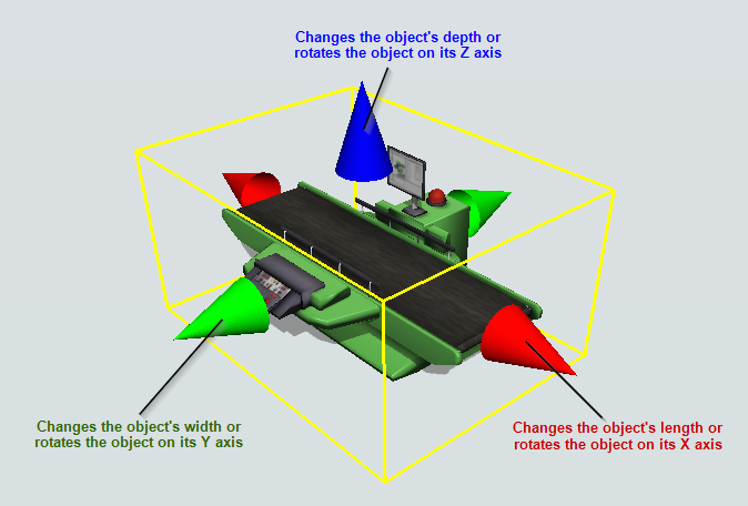
Each of the different colored axis arrows can change either the X, Y, or Z axis of the object's size and rotation (as shown in the following image):
- Red axis arrows - Located on the right and left of the object, the red axis arrows change the object's length or rotates the object on its X axis
- Green axis arrows - Located on the front and back of the object, the green axis arrows change the object's width or rotates the object on its Y axis
- Blue axis arrows - Located on the top and bottom of the object, the blue axis arrows change the object's height or rotates the object on its Z axis
The following image shows the axis arrows in action:
Using Properties
You might possibly want the location, rotation, and size of the objects to be more precise in your model. In that case, it might be better to use the Properties tool instead of using your mouse. This section will discuss some tips and tricks for setting an object's exact location, rotation, and size using Properties.
When you highlight an object in the model by clicking on it, the right pane displays the Properties for that particular object. In the Visuals panel, you'll see several different boxes for changing the object's position, rotation and size:
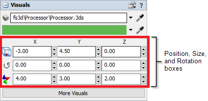
To the left of each row, you'll see three different graphical icons, as explained in the table below:
| Icon | Description | Point of Reference |
|---|---|---|
Position
|
Changes the object's position (location) within the model | By default, the object's position is determined by the coordinates of the object's bottom center. However, you can change this point of reference by clicking the Position button. See Changing the Location Point of Reference for more information. |
Rotate
|
Rotates the object | The object will rotate on its center axis. |
Resize

|
Adjusts the object's default size |
Every object in the FlexSim library has a default size. When you first created
the model, you set up the default units of measurement using the Model Units
dialog box. At that time, FlexSim automatically scaled the size of the objects
in the Library based on the units you specified. For example, a Queue in the FlexSim Library is 2 meters by 2 meters by .2 meters by default. If you specified feet as your unit of measurement, the default size of the Queue in the FlexSim library would change to 6.56 feet by 6.56 feet by 0.66 feet. |
Using each tool and its corresponding axis-coordinates, you can change the object's position, rotation, or size. The following table explains how each of the different tools can change the object based on the axis you are defining:
| X | Y | Z | |
|---|---|---|---|
| Position
|
Moves the object left and right on the X axis | Moves the object forward and back on the Y axis | Moves the object up and down on the Z axis |
| Rotate
|
Rotates the object on the X axis | Rotates the object on the Y axis | Rotates the object on the Z axis |
| Resize
|
Resizes the object's length | Resizes the object's width | Resizes the object's height |
Changing the Location Point of Reference
By default, the point of reference on the object that determines the object's location is the bottom center, as shown in the following image:
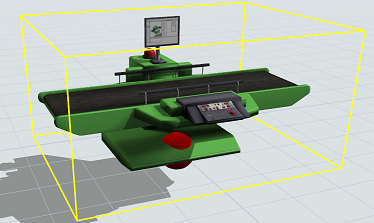
When you view an object's location in Properties, it displays the location coordinate for this point of reference by default.
However, you can change the point of reference if needed:
- Click the object in the 3D model to select it.
- In Properties, click the Position button
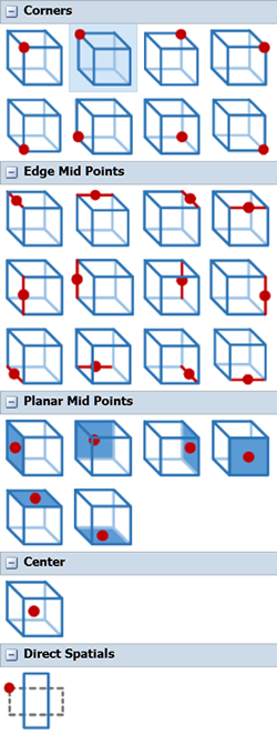
to open a menu:
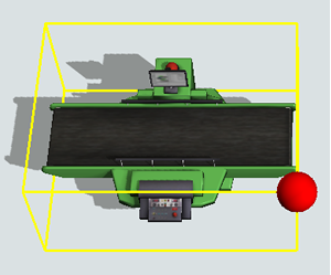
- As you mouse over a different point of reference, the 3D object will display the location of that point of reference is on the object, as shown in the following example:
- Select the desired point of reference on the object. Notice that the position settings in Properties will change to display the exact coordinates for this point of reference on the object, even though the object has not moved.
- Edit the coordinates as desired. The new location coordinates will be calculated based on this point of reference.
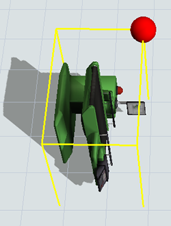
Rotation Affects the Point of Reference
Be aware that when you rotate the object, the point of reference will rotate with the object. For example, the following image shows the upper left object when it has been rotated 90 degrees on the Y-axis:
Direct Spatials
The Direct Spatials reference point works differently than all the above options. Selecting this option will display the position of the object as the spatial values of the object stored by the software. These spatial values are calculated off the back left corner on the bottom of the object before any rotations are applied. Because this value is not very useful after an object has been rotated, this mode is not normally recommended.
This mode is useful when you want direct access to the values stored by the software, for example, when using the position of the object as an experimenter variable.
Setting or reading the object's location through code will generally return these Direct Spatials values. However, you can use the Object's setLocation and getLocation methods which allow you to additionally specify the Point of Reference.