Robot Motion Paths
Robot Motion Paths
This is the most advanced mode that allows the user to design paths for the robot to follow. By default, the Robot contains 2 paths (called Load and Unload) to demonstrate some of the parameter options.
What is a Path?
A Path is a set of movements as defined by a series of
robot positions. The Robot stores robot positions
in a tabular format where each row is a record of the 6 joint angles
that make-up the
given position. The default Load
path for example contains 2 positions. When the
Robot performs this path, it will move from its current position to
Row1 position, followed by Row2 position. You can preview the motion of
the robot for this path by pressing the  button.
You can also directly view an individual row's position by clicking on
the row in the table and pressing the
button.
You can also directly view an individual row's position by clicking on
the row in the table and pressing the  button to
apply that row to the Robot's joints.
button to
apply that row to the Robot's joints.
What controls the timing of a Path movement?
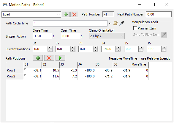
There are various options for controlling the time a path movement takes in the simulation. Note that the Gripper Action Times are added to the end of a movement.
- If Path Cycle Time
> 0 -
You can specify the length of time the Robot takes to complete the
series of path movements. In this case, the
MoveTime column in the Position Table affects the distribution of the
Path Cycle Time delay time as follows:
Without Weighting - Leave the MoveTime column in the Position Table all zeros or equal values and the Path Cycle Time will be divided evenly amongst the number of positions in the path.
With Weighting - Adjust the values in the MoveTime column to represent the ratio of the Path Cycle Time you wish to assign to each position row.
Example - A path contains 3 position rows with 1, 1, 2 respectively in the MoveTime column and the Path Cycle Time was 5.2s. The AR would take 1/(1+1+2) * 5.2s to move to the first position, an equal time to move from the first position to the second position, and 2/(1+1+2) * 5.2s to move from the second position to the third position.
- If Path Cycle Time = 0 and MoveTime column fields > 0 - When the Path Cycle Time field returns a 0, the Robot will use the sum of the values in the MoveTime column as the cycle time for the path. In this way you have precise control of the move time from each position to the next. This method can also be used to insert a stop delay in the movement; set 2 rows in sequence to the same position and use the MoveTime as the delay time.
- Negative Move Time affects animation only (Relative Speeds) - For a given movement within a path, if the MoveTime value is a negative value the Robot will still treat it as if it were positive, however the joint speeds will be adjusted such that they are proportional to the Relative Speeds entered in the Robot Geometry tab. Note that this is purely a change in the animation and does not affect the movement cycle time. Usually, entering the actual max speed of each joint (from manufacturer) into the Relative Speeds will give best results.
How do I create my own Paths?
- Position and size the model view such that you can see the
Robot Properties GUI and the robot in your model without overlap of
windows.
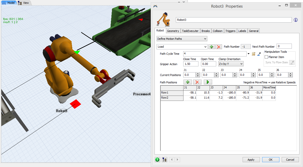
- Click Add Path. This will create a duplicate of the currently selected path.
- In the path's name field type a descriptive name for the path. The name has no functional effect on the behavior of the Robot.
- Clear the Position Table by pressing
 until there
is only one row remaining.
until there
is only one row remaining. - Turn ON the Path Planner by clicking the Planner Item checkbox. A box named PlanningItem will appear in the 3D view in the Robot’s gripper. You can move and rotate the PlanningItem with your mouse and the robot will move accordingly. You should have the Resize and Rotate Objects feature checked (found under Flexsim’s Edit menu). Also, you might consider disabling Snap To Grid before proceeding further.
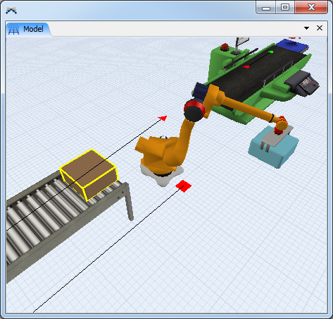
- Begin by recording the end position of your path as it is
the most important position. In this case, I wish to record a second
path for the Robot to follow before loading the FlowItem from the
conveyor. Thus, the end position would have the robot gripped onto the
FlowItem as it sits on the end of the conveyor.
- Press the model Step
button (in the simulation run panel) to advance the model run forward
by event until a FlowItem appears at the end of the conveyor ready for
pickup. You may need to recheck the Planner Item
checkbox if you reset the model since the robot hides the item when the
model is reset.
- In the Robot properties window, click the Sync to Flow
Item
 button
next to the Planner Item check box. The cursor will change to a
"sampling" cursor. Now click on the flow item in the model
view.
button
next to the Planner Item check box. The cursor will change to a
"sampling" cursor. Now click on the flow item in the model
view.
- Choose an option from the Clamp Orientation drop-down to determine the orientation from which the clamp will grab the flow item.
- Make sure to choose the proper
Close Width drop-down option for determining closed grip
width associated with this path. (The open gripper width parameter
is found in the Geometry tab)
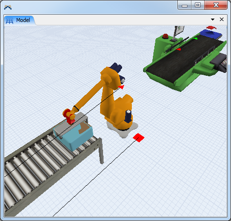
- Now
that the Robot is gripping the item as desired, save the Robot's joint
positions to the row in the table. Click on the first row in the table,
and press the
 button
to save the Robot's current joint positions to that row.
button
to save the Robot's current joint positions to that row. - The recorded position is actually the end
position the Robot must have at the end of a LOAD task (call it the
pickup position). Technically this is all you need, however often you
will
want to insert position rows above this row that control how the Robot
gets to the pickup position. For example you may want to have the Robot
first go to a position above the flow item, then drop down to clamp it.
To do this, add a new row by clicking on the first row and clicking the
 button.
This will add a row before the selected row. Then click on the
PlanningItem and use the scroll wheel on your mouse to change the Z
location of the PlanningItem while staying directly above the pickup
position. Then click on the newly created row in the table and press
the
button to update that row with the new position.
button.
This will add a row before the selected row. Then click on the
PlanningItem and use the scroll wheel on your mouse to change the Z
location of the PlanningItem while staying directly above the pickup
position. Then click on the newly created row in the table and press
the
button to update that row with the new position. - If you were to reset and run the model, the Automatic Path Selection would likely not choose your new path to load the FlowItem because the original Load path still exists and is positioned higher in the Path Selector list. Choose the original Load path and delete it.
- Reset and Run the model.
- Press the model Step
button (in the simulation run panel) to advance the model run forward
by event until a FlowItem appears at the end of the conveyor ready for
pickup. You may need to recheck the Planner Item
checkbox if you reset the model since the robot hides the item when the
model is reset.
How are the Gripper Action Times applied?
The Gripper Action Times are added to the Path movement time since a close or open clamp action is performed at the end of a LOAD or UNLOAD task respectively (after the path movement is complete).
- If you enter a positive value into the Close Time field, the Robot will close its clamp at the end of the Path movement and the value entered will be the delay time associated with the action. Note that if the Robot is responding to a task that does not involve a FlowItem, the closed clamp width will be 0.
- If you enter a positive value into the Open Time field, the Robot will open its clamp at the end of the Path movement and the value entered will be the delay time associated with the action. The clamp will open to the Open Gripper Width specified in the Geometry tab.
- If both the Close Time and Open Time fields are 0, the clamp will not move.
- If you enter a negative value into either the Close Time or the Open Time fields, the Robot will perform the action in 0 time. (as of FlexSim v5)
How does the Robot choose which Path to use?
By default, the robot searches for the path with an end position (last position row) which results in the smallest distance between the Robot’s end effector and x,y,z location as requested by the task it is responding to.
Controlling the Path that the robot uses for a given task
There are two ways to override the Robot’s automatic path selection. It is helpful to understand that the default task sequence that is generated when the Use Transport is checked on a Fixed Resource contains 2 tasks that the Robot responds to (FRLOAD and FRUNLOAD tasks).
- Specify directly on a custom Task Sequence - Knowledge of writing your own custom task sequences is assumed in this section. Specifying a negative end speed variable when writing the task sequence will tell the Robot to use the path number that matches this end speed (Path Number = end speed). The task types that the Robot responds to are listed below with the location of the end speed variable. See the Task Type Quick Reference found in the User Manual under Task Sequences.
- (As of FlexSim v5) When using a TRAVELRELATIVE task type with a negative endspeed to choose the path you can now use var1 (the x parameter) to tell the Robot which position row to stop at if you don’t want it to perform the entire path.
- Next Path Number (great for known path sequences such as palletizing) - Palletizing is simply a sequence of LoadPath1-UnloadPath1-LoadPath2-UnloadPath2… once the Robot unloads the last FlowItem on the Pallet, the sequence repeats. Every Path has a “Next Path Number” field in which you can specify the path number you want to be used following the currently selected path. When the Robot executes a path that has a non-zero Next Path Number specified, it will store this path number into memory until the next time in the model run it performs a task that requires automatic path selection (not specified on the task itself). Instead of searching for a suitable path, the Robot will choose the path number stored in memory.
- If during the model run you wish to clear the Robot’s Next Path Number memory, simply set its “nextpathselected” variable to zero and the Robot will return to conducting automatic path selection for a best-fit path (if not specified on the task).
- A combination of a custom task sequence and Next Path Number can save a lot of time!
- Take the example of a palletizing operation with 4 FlowItems per pallet.
- Make 1 load path and 4 unique unload paths to show the positioning of FlowItem on the pallet. The load path will be Path Number 1, and the unload paths will occupy Path Numbers 2 through 5. Don’t forget about the trick using the model “Step” and the “Match Highlighted Item” buttons we learned in “How do I create my own Paths?”.
- The path sequence we want is LoadPath1-UnloadPath1-LoadPath1-UnloadPath2- LoadPath1-UnloadPath3- LoadPath1-UnloadPath4 or Path Numbers 1-2-1-3-1-4-1-5. Since the LoadPath1 is always used for the FRLOAD task, we can specify var2 as -1 on this task.
- In the Path Planner, go to the load path (Path Number 1 in this example) and specify a Next Path Number = 2, as this is the first unload path of the cycle.
- Go to the first unload path (Path Number 2 in this example) and specify a Next Path Number = 3 (-3 will work as well). Path Number 3 should have a Next Path Number = 4, and Path Number 4 should have a Next Path Number = 5. Path Number 5 should have a Next Path Number = 2 to complete the cycle.
| TASKTYPE_ | Location of end speed variable |
|---|---|
| LOAD and FRLOAD UNLOAD and FRUNLOAD |
var2 |
| TRAVELRELATIVE TRAVELTOLOC (for movements that don’t involve FlowItems) |
var4 |