Conveyor System Properties
Overview and Key Concepts
The Conveyor System properties window can be used to set the default properties for all conveyor objects in your simulation model. It has two tabs with various properties, which will be explained in the following sections.
Accessing Conveyor System Properties
To access the Conveyor System Settings dialog box, you must first ensure that there is at least one straight or curved conveyor in your model. Otherwise, the Conveyor System tool will not appear in your toolbox. Once you have a conveyor in your model:
- Click View on the main menu, then click Toolbox to open the Toolbox. Alternatively, you could access the Toolbox by clicking the Tools button on the toolbar.
- You'll see several different tools listed in the toolbox. Double-click Conveyor System to open the Conveyor System Settings dialog box.
The General Tab
The General tab has the following properties:
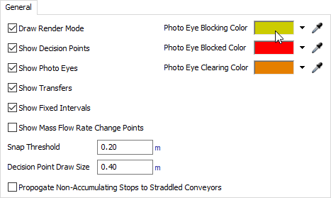
Draw Render Mode
When checked, straight or curved conveyors will visually appear to have rollers (for accumulating conveyors) or belts (for non-accumulating conveyors). See Conveyor Visualizations for visual options for simulating roller conveyors.
Show Decision Points
When checked, decision points will appear as a diamond icon on a conveyor.
Show Photo Eyes
When checked, photo eyes will appear as a green or red line across a conveyor.
Show Transfers
When checked, transfers will appear as a square icon on a conveyor.
Show Fixed Intervals
When checked, conveyors will show a line on a conveyor indicating where the dogs are in a Power and Free conveyor system. See Conveyor Types - Power and Free Settings for more information.
Show Mass Flow Rate Change Points
When checked, mass flow conveyors will show the lines that separate different densities on the conveyor. See Mass Flow Conveyor for more information.
Snap Threshold
Conveyors will snap and join together when they are within range of the value indicated in this field.
Decision Point Draw Size
Determines what size decision points should be drawn visually.
Propogate Non-Accumulating Stops to Straddled Conveyors
If checked, stopping/blocking items that are straddling multiple non-accumulating conveyors will also stop all upstream conveyors they are straddling (instead of just the conveyor that is driving the item's speed).
Photo Eye State Colors
These three color panels let you define the colors with which to draw photo eyes that are in the Blocking, Blocked, and Clearing states respectively.
The Defaults Tab
The Defaults tab has the following properties:
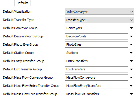
You'll notice there are two fields with pull-down menus. From each pull-down menu you can select the default types that are assigned to various conveyor objects when they are first added to the simulation model.
For more information about the Type Properties dialog box and different settings for each object, see:
There are also several fields for defining default groups. Here you can enter a name of a group. When objects are added to the model, they will be automatically added as members of the defined group. This is especially useful for categorizing your objects as you build your model, in order to subsequently filter or sort by their group membership when using Property Tables.