AGV Network
Overview and Key Concepts
The AGV Network helps you to create travel paths while simulating automatic guided vehicles (AGVs) and other task executers.
The AGV module does not add its own AGV object type to the library. Instead you can attach any task executer ( TaskExecuter, Operator, Transporter, etc.) to a control point on an AGV network, and that task executer will travel using AGV-defined logic.
The AGV Types Tab
For information on the AGV Types tab, see AGV Types.
The Control Point Connections Tab
For information on the Control Point Connections tab, see Control Point Connections.
The Accumulation Types Tab
For information on the Accumulation Types tab, see Accumulation Types.
The Deallocation Types Tab
For information on the Deallocation Types tab, see Deallocation Types.
The General Tab
The General tab has the following properties:
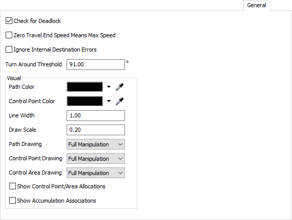
You can get to the General page by right-clicking on a Path or Control Point and choosing AGV Network Properties.
Check for Deadlock
If checked, the Control Point/Control Area allocation logic will continuously check for deadlock cycles. If it finds one, it will stop the model and notify you of the issue. Note that deadlock detection does require additional calculations and may slow your simulation down. You should hence turn it on while debugging, and once all deadlock issues are resolved, turn it back off.
Zero Travel End Speed Means Max Speed
If checked, AGV's will interpret travel tasks with end speed of 0 to mean: end at the AGV's max speed. This behavior is the default with other FlexSim travel mechanisms, such as standard travel networks that use network nodes. However, with AGVs this is not always the desired behavior, so it is an explicit setting that you define here.
Ignore Internal Destination Errors
If checked, travel destination errors caused when using AGV.BodyOffset.TrainLeadingEdge or AGV.BodyOffset.TrainTrailingEdge for a destination internal to the train body will not be printed to the system console. The AGV will instead immediately finish the travel task.
This error happens in a very specific case. If you want an AGV train's "leading edge" to travel to a destination on the AGV path network that is internal to the AGV train, then there is technically no way to successfully perform that operation, because whatever edge of the train travels to that destination will be the "trailing edge" not the "leading edge." Thus, giving the AGV such a task is technically an error. However, in some models it would be onerous to try to detect and avoid this error. Thus, you can check this box and the AGV will simply finish the travel task without moving at all.
Path Color
Defines the color by which Paths will be drawn in the 3D view. This is especially useful if you are overlaying your model with a CAD drawing, and want to delineate between AGV Network paths built in the model and CAD lines.
Control Point Color
Defines the color by which Control Points will be drawn in the 3D view.
Line Width
Defines a baseline width, in pixels, by which Paths and Control Points will be drawn in the model.
Draw Scale
Defines a baseline size by which to scale drawing of Control Points and Path direction arrows.
Path Drawing, Control Point Drawing, Control Area Drawing
Defines how the respective objects can be manipulated in the model. As you finish certain parts of your model you may want to restrict what you can change about the objects in it. Options are:
- Full Manipulation - You can click on and move these objects around as needed.
- Clickable Only - You can click on these object but you cannot move them around.
- Not Clickable - You can see the objects in the 3D view but you cannot click on them.
- Do Not Draw - You cannot see the objects in the 3D view.
Show Control Point/Area Allocations
Used primarily for debugging. If checked, the AGV network will draw each AGV's current and requested allocations in the 3D view. This includes allocations of control points, control areas, as well as path transfers. Current allocations are drawn in orange, whereas requested allocations are drawn in red.
Show Accumulation Associations
Used primarily for debugging. If checked, the AGV network will draw a lines between AGVs that are currently traveling on accumulating paths. It will draw a blue line from each AGV to the AGV ahead of it, and to the AGV behind it.
Way Points
Way Points are used to define AGV control logic that will happen when an AGV passes over a control point. However, going forward we advise you to use process flow instead of Way Points for AGV control. FlexSim provides a template AGV control process flow, which can be used as a starting point for defining AGV control logic..
The Way Points tab has the following properties:
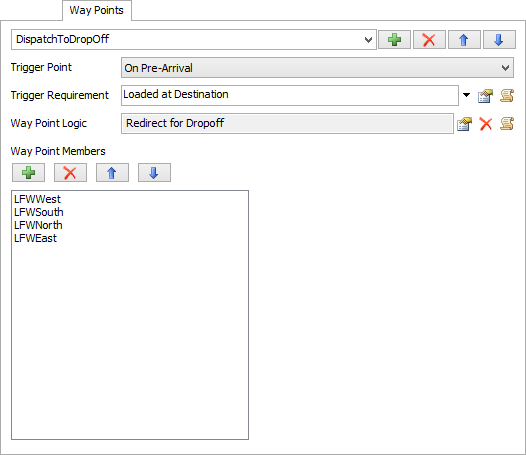
You can get to the Way Points page by right-clicking on a Path or Control Point and choosing AGV Network Properties.
Way Points List
Here you can add, remove, re-order, and rename each Way Point.
Trigger Point
This defines when to fire the Way Point Logic. Options are:
- On Pre-Arrival - The Way Point Logic will be fired at the point when the AGV would otherwise start to decelerate to stop at the Way Point.
- On Arrival - The Way Point Logic will be fired when the AGV arrives at the Way Point. Note that if the Trigger Requirement is met and this Trigger Point is chosen, the AGV will slow to a stop at this Way Point and then fire the Way Point, even if the Way Point is not the AGV's final destination. Hence if you don't want the AGV to slow to a stop, you should use On Pre-Arrival.
Trigger Requirement
A field that should return 1 if the Way Point should be fired, 0 if not.
Way Point Logic
The code for the Way Point.
Way Point Members
The list of Control Points that are part of this Way Point. Here you can add, remove and re-order the members list.