Creating Conveyor Logic
Introduction to Conveyor Logic
This topic will explain how to create different types of flow logic using conveyor objects. It will cover the most common conveyor systems that you might want to create. Before reading this topic, make sure you are familiar with the concepts explained in Key Concepts About Conveyors.
Using Conveyor Logic Objects
Decision points, stations, and photo eyes are the primary conveyor objects that are involved in controlling conveyor logic. For the sake of brevity, this guide will refer to these three types of objects as conveyor logic objects.
To use these objects, first you need to add one of them to a conveyor. Make sure that the object is at the point on the conveyor where you want something to happen to a flow item (such as diverting the item to a different conveyor line, delaying and processing the item, changing a label on a item, etc.).
Next, open the object's properties and apply the logic you want to the appropriate trigger. All three of the conveyor logic objects come with a set of pre-programmed picklist options that simulate some of the most common logic. You can use these picklists, or you can write your own custom logic with FlexScript.
For example, imagine you need to simulate a flipper on a conveyor that will mechanically rotate items 90 degrees so that they are aligned the correct direction. You could simulate this logic using a decision point and set its On Arrival trigger to use the Rotate Item logic:
You can also create port connections between decision points, photo eyes, and stations so that they can reference each other, possibly sending flow items or information to each other.
For example, imagine you wanted to randomly divert 30% of flow items to a separate conveyor. You could simulate this logic using two decision points. One is on the main conveyor line and another is on the diverting conveyor line. You would then create port connections (A-connects) between the two decision points. Next, you'd set the On Arrival trigger on the first decision point to use the Send Item logic to divert 30% of the flow items to the second decision point:
Which Conveyor Logic Object Should I Use?
The conveyor logic objects all have the same basic logical functionality: they all have triggers that are capable of executing pre-programmed or custom logic when a flow item passes over them. However, there are small differences between decision points, stations, and photo eyes that are good to be aware of:
- Triggers - The names of the triggers are slightly different for some of the objects. These triggers also fire at different times during a simulation. Decision points and stations have On Arrival and On Continue triggers while photo eyes have On Block and On Clear triggers.
- Process Times - Decision points and stations are nearly identical, but stations add some additional functionality that make them similar to the 3D processor object. You can add a processing time, require an operator, and specify the conditions under which an item should or should not be processed at the station. Stations also have an additional On Process Finish trigger.
- Gapping Logic - Photo eyes have the ability to respond to conditions in which they are blocked or clear, such as when there is a backup of flow items on the conveyor. You can also set the conditions that determine how long the photo eye needs to be covered or uncovered before it can be considered blocked or cleared. You can also set things like the angle of the photo eye and the visual colors of the photo eye when it is in a blocked or cleared state.
Use the appropriate conveyor logic object based on the functionality needed in your conveyor system.
Additional Conveyor Logic Objects
The merge controller and motor objects are also important to conveyor logic, but they will be explained in more detail in the following sections. Merge controllers are used primarily when merging slug-building conveyors (see Merging for more information). Motors are useful for power and free systems and for connecting multiple conveyors so that they all operate at the same speed and can be turned on or off simultaneously (see Power and Free Systems for more information).
Overview of Trigger Picklist Options
The following table provides a general overview of some of the pre-programmed picklist options that are available on the triggers for conveyor logic objects:
| Name | Description |
|---|---|
| Send Item | Can send items to different destinations (such as different conveyor lines) based on criteria you specify. See the section on Sorting for more information. |
| Stop/Resume | Can set conditions that can make a conveyor motor stop or restart. See the section on Stopping or Starting a Motor. |
| Stop Item and Delay | Can stop and/or delay an item |
| Area Restriction | Can create an area that only allows a fixed number of items to flow through a restricted area on the conveyor at a time. See Area Restriction for more information. |
| Movement | Can rotate, tilt, or move items at a particular point on a conveyor. See Flow Item Movement for more information. |
| Set Conveyor Speed | Can change the speed of the conveyor based on certain conditions |
Sorting
Conveyor systems use sorting (sortation) when items need to be transported to different destinations based on certain criteria. To simulate sortation conveyor systems in FlexSim, you'll need to use a conveyor logic object (a decision point, station, or photo eye). These objects have a pre-programmed picklist option called Send Item that can sort items based on certain criteria and then send them to various destinations through its port connections.
The Send Item picklist option has two properties that determine how it should sort items:
- Condition - This property decides "Should I divert this item?" and sorts items based on particular conditions.
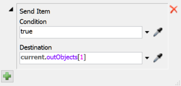
- Destinations - This property decides "If the condition is met, which destination should I send the item to?" and sorts items to multiple possible destinations based on criteria you define. This property usually points to another conveyor logic object or transfer that is connected to its output port(s).
You can use a combination of different settings in these two properties to build complex sorting logic into your conveyors.
The following sections describe some of the common sortation systems that you can build in FlexSim.
Conditional Sorting
Conveyors can sort flow items based on a simple true or false condition. If a flow item meets the condition in the Send Item Condition property, it will get diverted to the conveyor logic object's output port.
For example, in the conveyor system shown in the following image, 30% of the flow items will meet the condition and will be diverted to an alternate conveyor line. The On Arrival trigger for the first decision point is assigned the Send Item picklist behavior. The Condition property is set to randomly return a true value 30% of the time. When it returns a true value, it sends the flow item to the diverting conveyor line.
Destination-Based Sorting
Conveyors can also sort flow items based on the destination. The Send Item Destination property returns a reference to an object. This object should be a conveyor logic object or an exit transfer on the item's current conveyor.
For example, in the conveyor system shown in the following image, flow items are sent to the conveyor that matches the number in the type label on the flow item. There are five different flow item types (each with a different color). The On Arrival trigger for the first decision point is assigned the Send Item picklist behavior. The Destination property is will evaluate the type label on the item and send it to the output port that matches that number.
Fixed Resource Sorting
In the same way that you can sort items using the Send Item picklist to send items to a conveyor, you can also send items to a downstream fixed resource.
For example, the conveyor system shown in the following image is similar to the simulation model in the previous section. However, the last conveyor has a decision point that sends items to the queue connected to a particular exit transfer based on their type label.
Merging
Merge conveyors can organize items flowing from multiple infeed conveyor lines. The most common purpose of merging is to combine items from multiple conveyor lines into a single line, which then sends the items downstream for further processing. This section will describe how to use FlexSim conveyor objects to create various kinds of merges. It will also discuss accumulation methods that could possibly be used when merging items.
Basic Merging
You can create simple merges by snapping conveyor lines together and using conveyor logic objects.
Slug Building
The conveyor industry uses the term slug to refer to a queue of accumulated items on a conveyor that will eventually be released downstream as a single group. Building slugs of items can maintain high rates of throughput while keeping equipment speeds as slow as possible.
You can design a conveyor that builds slugs and waits to release them based on a specific set of criteria such as:
- What percentage of the conveyor must be filled before a slug is ready for release
- The number of items that must be on a conveyor before a slug is ready for release
- The amount of time that must elapse in building the slug before a slug is ready for release
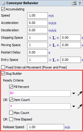
For example, in the following image, each conveyor in this system is set to build a slug of at least four items before it can be released:
In the properties for your conveyor:
- Check the Slug Builder check box to enable slug building.
- Then, in the Ready Criteria, check the boxes next to
the conditions you would like the conveyor to use when determining a slug is complete
and ready for release.
Sawtooth Merging Using the Merge Controller
The merge controller object can be used to reduce the gaps and prevent collisions between slugs as they move onto the merging conveyor. Its logic is defined by its two main properties: 1) Release Strategy, and 2) the Lane Clear Table. These two properties determine how it will prioritize merging lanes.
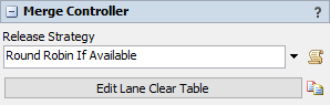
![]()
The Release Strategy has two pre-programmed options: round robin logic or first available logic. If you are comfortable with FlexScript, you can also create your custom release strategy.
The Lane Clear Table prevents merge jams and shortens the gaps between slug releases. The rows and columns are automatically be generated based on the objects the merge controller is connected to, but you can edit the table to change the order in which rows and columns are listed. The X's in the columns define which decision point (or other conveyor logic) needs to be cleared before the merge controller can release a slug from a particular lane.
In the following image, the merge controller communicates with decision points to close the gaps in between slug releases:
Sawtooth Merging Using Process Flow
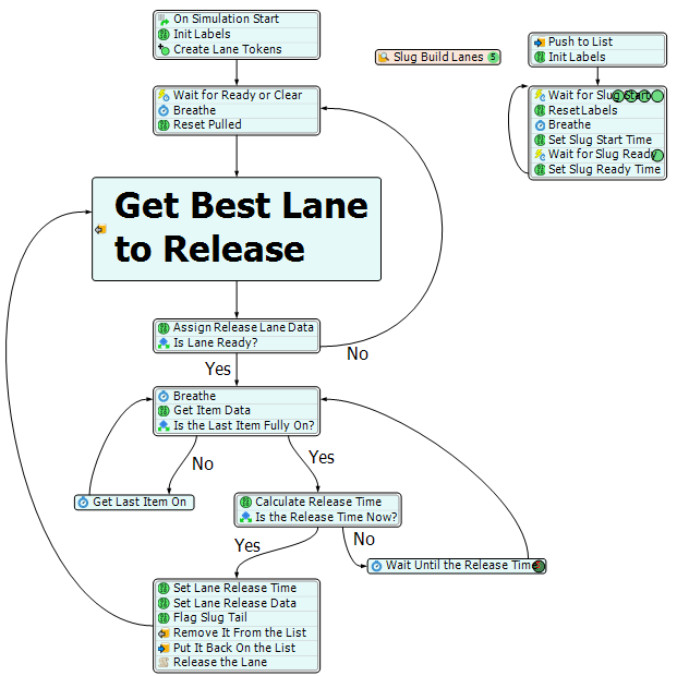
You can use a template Process Flow to create logic that will close the gaps in between slugs even more. The following image is an example of a merging conveyor system that uses process flow to determine the ideal release rate:
To add this process flow to your model, press the Process Flow button on the main toolbar, then choose Add an Object Process Flow > Gap-Optimizing Merge Controller. Then attach an existing merge controller to that process flow.
Here is the process flow that manages this merge:
Power and Free Systems
Power and free conveyor systems are implemented in many manufacturing environments. In these systems, dogs travel at fixed intervals along a looping chain. These dogs pick up carrier trolleys in the system as they pass them.
FlexSim simulates power and free systems by tracking the location of dogs on a conveyor or conveyor system. The point at which an item can move on the conveyor is defined by the location of the next passing dog. When an item is ready to move, it catches a dog. Often the movement of items has a caterpillar-like accumulation effect.
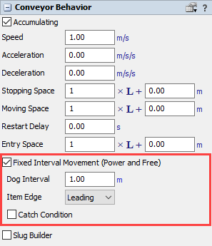
In the properties for your conveyor:
- Check the Fixed Interval Movement (Power and Free) checkbox to enable power and free behavior.
- If needed, change any of the other power and free properties (such as which item is
the leading edge or the spacing in between the dogs).
Using a Motor to Sync Dogs
Although you are not required to use a motor in a power and free system, using a motor is recommended. Motors can help sync the dog positions across multiple conveyors in a power and free system. For example, if the motor's first connected conveyor is 10.2 meters long, and the dog gap is 1.0 meters, then it will set the dog position to start at 0.0 on the first conveyor and at 0.8 on the second connected conveyor (the remaining distance to the next dog after the end of the first conveyor). The motor prevents the conveyors from creating irregular gaps or stops when transferring items between conveyors.
To use a motor with a power and free system:
- Connect a motor to all of the power and free conveyors in the order that items will flow from one conveyor to another.
- Click the motor to open its properties window on the right. Check the Sync Power and Free Dog Positions box under the Motor section.
- If you are using the motor to sync the dog positions across an entire loop, check the Adjust Dog Gap for Continuous Loop box.
Creating Overhead Conveyors
To create an overhead power and free system you'll need to translate the z-axis of the item:
- Put a conveyor logic object (a decision point, station, or photo eye) at the beginning of the first conveyor in the power and free system.
- Click on the conveyor logic object to open its properties window on the right. In the
Triggers section, click the Add
button
 to open a menu of possible triggers.
Select either On Arrival or On
Block.
to open a menu of possible triggers.
Select either On Arrival or On
Block. - Click the Add button
next to the newly added trigger to open a
menu. Select Movement then, Translate
Item.
- Set the Conveyor Up setting to a negative number, such
as
-item.size.zor-2, and it will hang below the conveyor while moving.
Stopping or Starting a Motor
Conveyor logic objects (decision points, photo eyes, stations) can be set to stop, delay, and/or start a conveyor's motor when certain conditions are met. For example, if a photo eye is blocked, it can stop the motor until the photo eye is clear again. Any conveyors that are connected to the motor will be stopped until the motor resumes.
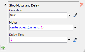
You can use the Stop Motor or the Stop Motor and Delay picklist behavior option on a conveyor logic object to stop a conveyor. Just make sure you also add a condition under which the motor will restart again using the Resume Motor picklist behavior.
In order to effectively stop a motor, ensure the following conditions are met:
- Connect the motor to the conveyor logic object(s) with a center port connection (an S-connect).
- Connect the motor to all the conveyors it should control (with A-connects).
- Add the Stop Motor or Stop Motor and Delay picklist behavior to the appropriate triggers on a conveyor logic object. Determine which conditions should cause the motor to stop and add those to the Condition property.
- Make sure that there is a condition under which the motor will restart again. Use the Resume Motor picklist behavior on the appropriate trigger to create this condition.
Flow Item Movement
You can use a conveyor logic object (decision point, station, or photo eye) to move or change a flow item when it passes over it. The triggers on conveyor logic objects have pre-programmed picklist behaviors to help with many of the common movement actions you might want to do. Use the Movement submenu on a trigger if you want to change the item's location or orientation (rotation, tilt angle, etc.). The Movement submenu has two options: Rotate Item and Translate Item.
The Rotate Item picklist rotates the item as it passes over the logic conveyor object.
The Translate Item picklist moves the item's position relative to the conveyor.
![]()
See Creating Overhead Conveyors for step-by-step instructions about using the Translate Item option.
The Rotate Item and Translate Item options use kinematics-based offsets. When you use one of these picklist options, be aware they don't change the item's properties, logic, or orientation (with some exceptions, as noted below). Their logic is mostly just visual. Keep in mind:
- You will likely not want to translate the item along the conveyor-forward axis (forward or backward along the conveyor) because it might make other conveyor logic fire at strange points visually. That's because the item has been visually offset forward or backward from the location where the conveyor is actually tracking it.
- If items are offset on the conveyor-left axis, and they pass over photo eyes with an offset angle applied, they will still cover/clear the photo eye as if they were in the center of the conveyor.
However, there are some exceptions to this visual-only rule:
- When an item starts a side transfer, the transfer logic will take the item's conveyor-left offset into account in determining how far the item must move to complete the transfer.
- If a photo eye's height is non-zero, then when an item's front edge reaches the photo eye, the cover logic will take the item's current conveyor-up offset into account in determining whether the item covers the photo eye.
Area Restriction
Area restriction can be used to restrict access to a particular conveyor or a segment of a conveyor. For example, you could create an area that only allows one flow item into the area at a time, as shown in the following image:
To create an area restriction system:
- Add at least two conveyor logic objects (such as decision points or photo eyes) to the conveyor system. The upstream conveyor logic object(s) will designate the entrance to the restricted area and the downstream conveyor logic will designate the exit for the restricted area.
- Create an input/output port connection (A-connect) from the upstream conveyor logic object to the downstream one.
- Add an appropriate trigger to the conveyor logic object (such as an On Arrival or On Block trigger.)
- On the newly added trigger for the upstream conveyor logic object(s), add the Acquire Restricted Area picklist option.
- Add another trigger to the downstream conveyor logic object. Then, add the Release Restricted Area picklist option to that trigger.
You can work through a few examples of area restriction in Conveyors Tutorial 1.2 - Merging, Area Restriction, and Slug Building and Conveyors Tutorial 1.3 - Adding and Removing Gaps.
Adding and Removing Gaps
You may or may not want gaps between your flow items when you merge one conveyor lane into another.
Adding Gaps
The Area Restriction picklist can actually be effective for adding gaps to a conveyor line. It can be used to add both fixed and variable gapping to flow items. See Area Restriction for more information.
Removing Gaps
Usually the primary reason why you want a conveyor system is to reduce gaps between flow items, which increases your system's overall throughput.
If you want to remove gaps in between merging flow items, you can do one or all of the following steps:
- Change the conveyor angles - Change the angle of the feeding conveyor relative to the merging conveyor, possibly using the Join Conveyor tool to create curved conveyor sections between these conveyors.
- Adjust the transfer settings - Adjust the angle settings for the transfer between the conveyors to increase or decrease the threshold at which the angle is considered a side or inline transfer. See Side and Inline Transfers for more information.
- Use more decision points with a merge controller - Increasing the number of decision points along the merging conveyor line can increase the rate at which a merge controller releases slugs.
- Use the process flow template - The merge controller process flow template can decrease gaps and improve throughput dramatically.
The step-by-step process for removing these gaps will be explained in Conveyors Tutorial 1.3 - Adding and Removing Gaps. This tutorial has additional tips and techniques you can use to affect gapping in conveyors.