Task 4.1 - AGVs Using Standard 3D Logic
Task Overview
When you complete this tutorial, you'll eventually build an AGV network for an entire hospital. The AGVs will transport medical supplies, laundry, and waste to and from the loading dock area throughout the rest of the hospital.
For now in this first tutorial task, you'll focus on creating a very basic AGV network using only standard 3D logic. You'll learn how to create AGV paths and connect 3D objects to control points along those paths. You'll also learn how to add more than one AGV to the model.
When you're finished, your model will look similar to the following image:
Step 1 Add and Connect AGV Paths
In this step, you'll add and connect AGV paths together to create the main AGV network. This network will become a circular circuit on which AGVs will loop around continuously looking for tasks to work on. When you're finished with this step, your 3D model should look like the following image:
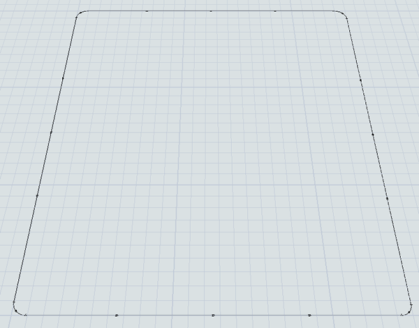
For the most part, AGV paths can be added, moved, resized, etc. using the same methods you would use for other 3D objects. However, the key difference is that AGV paths have two ends: respectively called the start and the end.
The start is where AGVs enter the path and the end is where AGVs leave the path. Although these two ends are connected, you can move them independently. Curved paths also have a radius, start angle, and sweep angle that you can use to control the arc of the path.
To create the AGV path layout for this 3D model:
- In the Library, click the Expand button
 next to the
AGV group to view the AGV objects.
next to the
AGV group to view the AGV objects. - Click the Straight Path to enter path building mode. When you are in path building mode, your mouse pointer will change to a plus sign with a Straight Path icon next to it, as shown in the following image:
- Once in building mode, find the position in your 3D model where you want to place the start of the AGV path. When you click on that position in the model and start moving the mouse pointer from left to right, you'll notice that it begins creating an AGV path.
- Reposition the mouse pointer until the path is 28 units away from the start. Eventually the main AGV looping path will be 25 units along the x-axis and 30 units long the y-axis, but you'll want to leave 1 unit of space on either end.
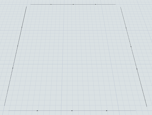
- Notice that you are still in path building mode. You'll build 3 additional paths.
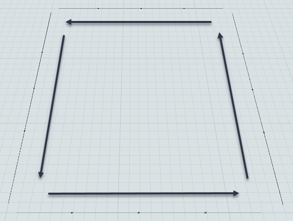
Try to build the paths into a square box shape that is approximately 25 by 30 units long
without connecting the paths together at the corners, as shown in the following
image:
- Press the Esc key to exit path building mode.
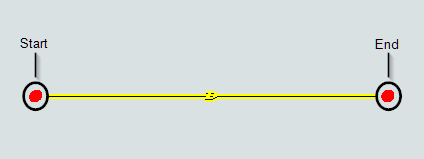
- Before joining these paths, check to ensure that the paths are oriented to move in a
counter-clockwise direction. The directional arrows on each path show you the direction
that the AGVs will move on this path:
- The south path should move from left to right
- The east path should move from down to up
- The north path should move from right to left
- The west path should move from up to down
- Now it's time to join the paths. In the Library under the AGV group, click the Join Paths object to enter path joining mode. When you are in path joining mode, your mouse pointer will change to a plus sign with a Join Paths icon next to it, as shown in the following image:
- While you are in joining mode, hover your mouse over the end of one of the paths until it turns yellow, as though it were highlighted. Click the path and start moving the mouse pointer to the end of the nearest path. Click the path when it turns yellow as though it were highlighted. The paths should now be joined.
- Join all the remaining paths together so that they form a closed circuit.
- Press the Esc key to exit path joining mode.


Consider saving your simulation model at this point.
Step 2 Add and Connect 3D Objects to the Network
In this step, you'll add a variety of 3D objects to the model:
- A queue that will act as the hospital's unloading dock where it will eventually receive shipments of medical supplies and clean laundry
- Two processors that will represent the amount of time it takes to stage the shipments for pick up by the AGVs at their loading stations
- A TaskExecuter object (because these objects visually look like AGVs by default)
- A sink that will temporarily act as a destination for the AGV when it unloads its shipments
Perhaps most importantly, you'll learn how to use an AGV object called a control point to connect 3D objects to an AGV network in this step. Control points are access points where fixed resources and task executers can interact with the AGV network. You'll connect the fixed resources to a control point so that they can call and receive transports. And you'll connect the task executers to the control point so that they can enter and travel on the AGV network.
Keep in mind that the AGV network is basically a more sophisticated way to transport flow items from one 3D object to another, but the basic transport logic is very similar to the standard method of transporting flow items using a task executer. For that reason, you'll need to make sure that all the objects are connected with port connections.
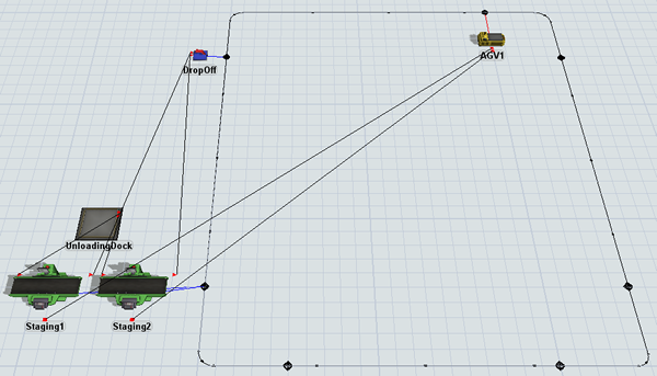
When you're finished with this step, your 3D model should look similar to the following image:
To add and connect these objects:
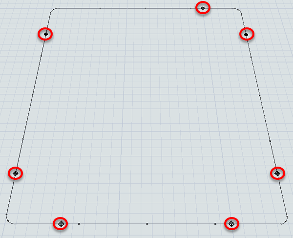
- In the Library under the AGV group, drag out seven Control Points and place two on each straight path except the top one. Place each control point about 5 units away from the sides of the paths, as shown in the following image:
- For clarity, rename a few of the new control points as follows:
- Add the following 3D objects from the Library into the 3D model:
- A Queue (near the MainPickUpPoint)
- 2 Processors (near the MainPickUpPoint)
- A Sink (near the MainDropOffPoint)
- A TaskExecuter (near the AGVEntryPoint)
- For clarity, rename the objects as follows:
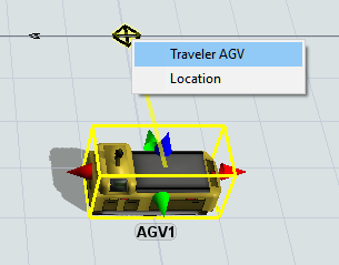
- Create a connection (A-connect) from AGV1 to the AGVEntryPoint control point to open a menu. Select Traveler AGV. A red line will appear showing the AGV is connected.
- Create connections (A-connect) for the following objects:
- From the Staging1 processor to the MainPickUpPoint control point
- From the Staging2 processor to the MainPickUpPoint control point
- From the DropOff sink to the MainDropOffPoint control point
- From UnloadingDock queue to Staging1 processor
- From UnloadingDock queue to Staging2 processor
- From Staging1 processor to DropOff sink
- From Staging2 processor to DropOff sink
- Create a center-port connection (S-connect) from the Staging1 processor to AGV1.
- Repeat the previous step to connect the Staging2 processor to AGV1 as well.
| Object | New Name |
|---|---|
| Control Point in the top east corner | AGVEntryPoint |
| Control Point in the upper west corner | MainDropOffPoint |
| Control Point in the lower west corner | MainPickUpPoint |
| Object | New Name |
|---|---|
| Queue | UnloadingDock |
| Processor1 | Staging1 |
| Processor2 | Staging2 |
| Sink | DropOff |
| TaskExecuter | AGV1 |
When you're finished, your model should look similar to the image shown at the beginning of this step.
Step 3 Set Up the Transportation Logic
In this step, you'll create the basic transportation logic that the staging processors will use to send items to the drop off sink using the AGV network. For now, you'll learn how to integrate AGVs into the standard 3D object logic. In a future step, you'll learn how to integrate it with process flow.
At the end of this step, you'll also set up a simple process flow that will handle the schedule for items that arrive at the unloading dock. For now, you'll set the schedule to only deliver two flow items that will immediately be processed by the two staging processors. In the future, you'll make this arrival schedule more complex. Keep in mind that the main goal in this step is mostly to test that the basic transportation logic is working.
When you're finished, your process flow will look similar to the following image:
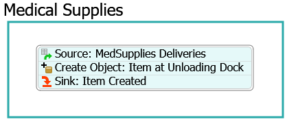
The following is an overview of how each activity will function:
| Activity | Explanation |
|---|---|
| Source: MedSupplies Deliveries | The Schedule Source is an activity that will create tokens at a specific time during a simulation model. For now, you'll set this activity to create two tokens when the simulation model begins. |
| Create Object: Item at Unloading Dock | This activity will create a box flow item and place it inside the UnloadingDock queue. |
| Sink: Item Created | This activity removes the token from the process flow. You'll use its default settings. |
To set up the transportation logic:
- Click Staging1 processor to bring up its properties on the right. Under the Output section, check the Use Transport box.
- Click the OK button to save the changes and close the properties window.
- Repeat the previous steps for the Staging2 processor as well.
- On the main toolbar, click the Process Flow button to open a menu. Select Add a General Process Flow to create a new process flow.
- In Properties, change the name of this new process flow to DeliverySchedule.
- From the library under the Display group, add a Container shape.
- For clarity, rename the shape Medical Supplies.
- Add the following activities to the process flow, creating a stacked block:
- A Schedule Source (under Token Creation)
- A Create Object (under Objects)
- A Sink (under Basic)
- For clarity, rename the new activities as follows:
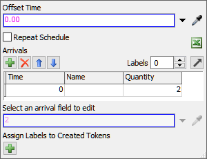
- Click the Source: MedSupplies Deliveries activity to
select it. In Properties, under the Arrivals table,
find the cell on the first row under the Quantity column.
Type
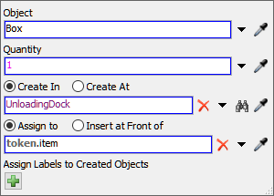
2in this cell. - Click the Create Object: Item at Unloading Dock
activity to select it. In Properties, check to ensure that the
Create In option is selected. Next the box under this
option, click the Sampler button
 to enter sampling mode.
 - In the 3D model, click the UnloadingDock queue to open a menu. Select UnloadingDock to sample it.
| Object | New Name |
|---|---|
| Source | Source: MedSupplies Deliveries |
| Create Object | Create Object: Item at Unloading Dock |
| Sink | Sink: Item Created |
Reset and run the model to test that the basic AGV transportation logic is working:
If you've set up your model correctly, the two processors will process two flow items. When they are done processing, the AGV will pick up one flow item and transport it to the sink. Then, it will loop back around again and pick up another flow item.
If your model isn't behaving as expected, go back and check that you've completed the previous steps in the tutorial correctly.
Step 4 Add a Second AGV
In this step, you'll learn how to add additional AGVs to the AGV network. If you are using standard logic to control the AGVs, you'll need to switch to using a dispatcher once you begin using more than one AGV.
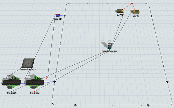
When you're finished, your 3D model will look similar to the following image:
To add a second AGV:
- Remove the center port connections that are connecting AGV1 to the Staging1 and Staging2 processors. (Press and hold the W key while clicking two connected objects.)
- From the Library add the following objects to the model:
- A Dispatcher
- A TaskExecuter
- For clarity, rename the objects as follows:
- Create a center-port connection (S-connect) from the Staging1 processor to AGVDispatcher.
- Repeat the previous step to connect the Staging2 processor to AGVDispatcher as well.
- Create port connections (A-connects) from the AGVDispatcher to both the AGVs.
- Drag AGV1 away from the AGVEntryPoint so that the control point is visible in the 3D model.
- Create a port connection (A-connect) from AGV2 to the AGVEntryPoint control point to open a menu. Select Traveler AGV. A red line will appear showing the second AGV is connected.
| Object | New Name |
|---|---|
| Dispatcher1 | AGVDispatcher |
| TaskExecuter | AGV2 |
Reset and run the model:
Notice that AGV2 gets deadlocked because AGV1 stays at the drop off point and won't move so that AGV2 can deliver the flow item. The reason why AGV1 doesn't move is because there are no more unloading tasks for it to work on. As a result, it just remains at its current position until it gets assigned a new task to work on. Since the current model only schedules two flow items to arrive at the unloading dock, there will never be any new tasks.
You could solve this problem by ensuring there is a continuous amount of work for the two AGVs to work on. You could also add more than one drop off point to the sink so that different AGVs can each deliver their loads to the sink without having a conflict. However, adding park points is easier when you use the AGV process flow template, which will be covered in the next tutorial task.
Conclusion
Now that you've built a very basic AGV model using only standard 3D objects and standard 3D logic, it's time to make this basic model a little more complex. In the next tutorial task, you'll learn how to use the AGV process flow template and you'll add some pick up and parking points to the model. Continue on to Tutorial Task 4.2 - AGVs Using Process Flow.