Task 3.1 - Build PLC Basic Ladder Logic
Task Overview
This tutorial will teach you the basics of building an emulation simulation project. Emulation is a term that refers to the ability to create simulated programmable logic controller (PLC) logic. If you are simulating a system that will eventually use PLCs, you can use emulation to develop and test the PLC logic within FlexSim without needing to create the ladder logic in other software. See Key Concepts About Emulation for more information.
In this tutorial, you'll simulate PLC logic that will control a conveyor. The conveyor's logic will be entirely handled by the emulation shared assets in process flow. The conveyor logic in this model will be fairly simple: you'll design a system that will delay a flow item on a conveyor for 5 seconds after it hits a photo eye.
When you're finished, the simulation model will work similar to the one shown in the following image:
While working on this tutorial, it's important to keep in mind the goal of an emulation project. In general, the goal is to design the simulation model in a way that will make it easy to communicate how to program the ladder logic in the actual system later. Using emulation, you can design the ideal logic that the PLCs in your system should use. Then, you can use FlexSim to communicate how that logic should work to the employee who will program the PLC for the actual manufacturing system. This tutorial will approach emulation with this goal in mind.
Step 1 Build the 3D Model
In this step, you'll build a basic 3D model for this tutorial. You'll add a few different conveyor objects for this particular model. When you're finished, your model should look similar to the following image:
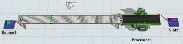
To build this model:
- Make sure your 3D model window is open and active. From the Library, drag the
following 3D objects into the model:
- A Source
- A Straight Conveyor (under Conveyors)
- A Processor
- A Sink
- A Motor (under Conveyors)
- Add a Photo Eye (under Conveyors) and place it approximately one third of the way along the Conveyor1.
- Create port-connections (A-connects) between the following objects:
- From Motor1 to Conveyor1
- From Source1 to Conveyor1
- From Conveyor1 to Processor1
- From Processor1 to Sink1
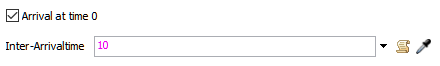
- Click Source1 to open its properties on the right. In Properties, under the Source section, check the Arrival at time 0 box.
- In the Inter-Arrivaltime box, delete the current text
and type
10.
Check to ensure your model looks similar to the image shown at the beginning of this step.
Step 2 Add Variables and Connections
In this step, you'll add some process flow shared assets to a general process flow. These shared assets will be the primary objects you will use any time you are building an emulation project.
Variables are any inputs or outputs that are received or sent by the PLC. In this model, you'll use three types of variables: a sensor (input), a control (output), and a connection (representing the server). You'll start by adding two variables, one for the conveyor's photo eye (which will be the sensor) and one for the conveyor's motor (which will be the control). At the end of this step, you'll link these two variables to the objects they represent in the 3D model.
You'll also create a variable for the server connection in this step. For now, this server connection will be inactive, which means that it will only be internal to FlexSim. FlexSim will act as the server when you run the simulation model. You'll read and write all values internally in FlexSim. You'd want to make this connection active in a later phase of the model building project in which you begin to test and validate the actual PLC logic.
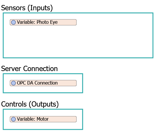
When you're finished, your process flow should look similar to the following image:
To add and connect these emulation shared assets:
- On the main toolbar, click the Process Flow button to open a menu. Select Add a General Process Flow.
- Drag 3 Container shapes (under Display) into the process flow.
- Rename the shapes as follows:
- Add 2 Variable shared assets (under Shared Assets, placing one in the Sensors (Inputs) shape and one in the Controls (Outputs) shape.
- Rename the variables as follows:
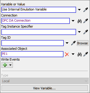
- Click the Photo Eye variable to select it. In Properties, click the arrow next to the Variable or Value box to open a menu. Point to Internal Emulation Variable, the point to Sensors (PLC Inputs), then select OPC DA Tag.
- Next to the Connection box, click the
Sampler button
 to enter sampling mode.
 - Click the blank space inside the Server Connection shape to open a menu. Point to Internal Connection, then select OPC DA Connection.
- If you clicked away from it, click the Photo Eye
variable to select it. In Properties, next to the Associated
Object box, click the Sampler button
to enter sampling mode.
- In the 3D model, click PE1 (the photo eye) to sample it.
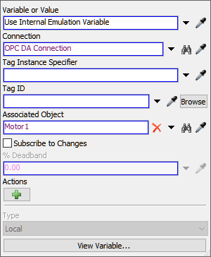
- Click the Motor variable to select it. In Properties, click the arrow next to the Variable or Value box to open a menu. Point to Internal Emulation Variable, then point to Controls (PLC Outputs), then select OPC DA Tag.
- Next to the Connection box, click the
Sampler button
to enter sampling mode.
- Click the OPC DA Connection variable to sample it.
- If you clicked away from it, click the Motor variable
to select it. In Properties, next to the Associated
Object box, click the Sampler button
to enter sampling mode.
- In the 3D model, click Motor1 (the conveyor motor) to sample it.
- If you'd like, you can resize the shared assets and shapes so that it matches the image at the beginning of this step. Leave space for more activities in the Sensors (Input) shape.
| Shape | New Name |
|---|---|
| First shape | Sensors (Inputs) |
| Second shape | Server Connection |
| Third shape | Controls (Outputs) |
| Variable | New Name |
|---|---|
| Variable in the Sensors shape |
Variable: Photo Eye |
| Variable in the Controls shape |
Variable: Motor |
Consider saving your simulation model at this point.
Step 3 Set the Variable Actions and Events
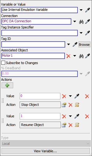
In this step, you'll set up the actions and events for the two variables you created in the previous step. The motor is a control, which means that it will read output values from the server and take a specific action in the 3D model based on that output. In this case, you'll set the conveyor's motor to stop when it receives a value of 0 from the server. It will resume when it receives a value of 1 from the server.
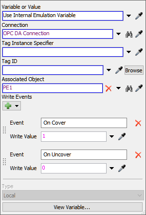
The photo eye variable is a sensor, which means it will write input values to the server when when certain events occur in the 3D model. When the photo eye is covered, it will write a value of 1 to the server. When the photo is uncovered, it will write a value of 0 to the server.
To set up the variable actions and events:
- Click the Variable: Motor to select it. In
Properties under the Actions group, click the
Add button
 to add a new action.
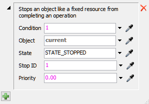
 - In the Value box, delete the current text and type
0. - Next to the Action box, click the
Add button
to open a menu. Point to Control, then select
Stop Object to open a picklist window. You'll use the
default settings for this picklist option.
- Under the Actions group, click the
Add button
again to add another action.
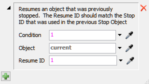
- In the Value box, delete the current text and type
1. - Next to the Action box, click the
Add button
to open a menu. Point to Control, then select
Resume Object to open a picklist window. You'll use the
default settings for this picklist option.
- Click the Variable: Photo Eye to select it. In
Properties under the Write Events group, click the
Add button
to open a menu. Select On Cover. You'll use the default
settings for this write event.
- Click the Add button
to open a menu. Select
On Uncover.
- In the Write Value box, delete the current text and
type
0.
Consider saving your simulation model at this point.
Step 4 Add Ladder Logic to the Process Flow
In this step, you'll add activities to a general process flow that will create the conveyor's ladder logic.
When you're finished, your process flow should look similar to the following image:
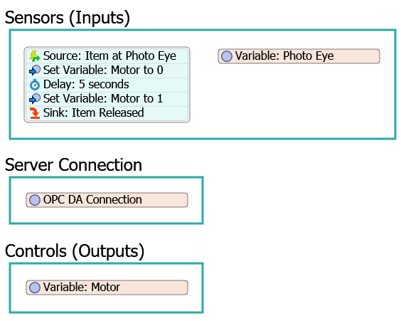
The following is an overview of how each activity and shared asset will function:
| Activity | Explanation |
|---|---|
| Source: Item at Photo Eye | The Event-Triggered Source is an event-listening activity that will listen to events in the photo eye variable. You'll listen for the On Change event, which means that it will listen for any time PE1 (the photo eye) is covered by a flow item. Recall from the previous tutorial step that when the photo eye is covered, it will write a value of 1 to the server. The source will listen for any changes on the photo eye variable. When a value of 1 is written to the server, the source will release a token to the next downstream activity. |
| Set Variable: Motor to 0 | This activity will set the motor variable to 0, which will stop the conveyor motor in the 3D model. |
| Delay: 5 seconds | This activity will delay the token for 5 seconds, which will essentially stop the conveyor for 5 seconds. |
| Set Variable: Motor to 1 | This activity will then set the motor variable back to 1, which will resume running the conveyor model. |
| Sink: Item Released | This activity will remove the token from the process flow and the flow item will continue along the conveyor. You'll use the default settings for this activity. |
To add and edit these activities:
- In the Sensors (Inputs) shape, add the following
activities to create a stacked block:
- An Event-Triggered Source (under Token Creation)
- A Set Variable (under Shared Assets)
- A Delay (under Basic)
- A Set Variable (under Shared Assets)
- A Sink (under Basic)
- Rename the activities as follows:
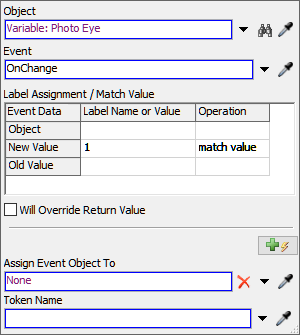
- Click the Source: Item at Photo Eye activity to select
it. Click the Exclamation Point button
 next to this activity to enter
sampling mode.
next to this activity to enter
sampling mode. - Click the Variable: Photo Eye shared asset to open a menu. Select Variable: Photo Eye: On Change.
- In Properties, in the Label Assignment / Match Value table, click the cell that is on the New Value row under the Label Name or Value column. Type 1.
- Click the cell that is on the New Value row under the Operation column to open a menu. Select match value.
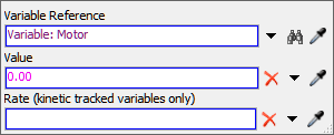
- Click the Set Variable: Motor to 0 activity to select
it. In Properties, next to the Variable Reference
box, click the Sampler button
to enter sampling mode.
- Click Variable: Motor to sample it.
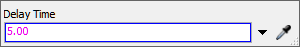
- Click the Delay: 5 seconds activity to select it. In
Properties in the Delay box, delete the current text
and type
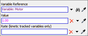
5.00. - Click the Set Variable: Motor to 1 activity to select
it. In Properties, next to the Variable Reference
box, click the Sampler button
to enter sampling mode.
- Click Variable: Motor to sample it.
- In the Value box, delete the current text and type
1.00.
| Activity | New Name |
|---|---|
| Source | Source: Item at Photo Eye |
| Set Variable (first one) | Set Variable: Motor to 0 |
| Delay | Delay: 5 seconds |
| Set Variable (second one) | Set Variable: Motor to 1 |
| Sink | Sink: Item Released |
Reset and run the model.
As you watch the simulation model run, notice that the flow item will hit the photo eye, setting in motion the logic that causes the conveyor's motor to turn off. After 5 seconds, the conveyor motor turns back on and the flow item continues moving down the conveyor.
Conclusion
At this point, you've learned how to emulate basic PLC logic in FlexSim. In the next tutorial task, you'll learn how to add area restriction to a conveyor so that you can see how the Get Variable activity works in a process flow. Continue on to Tutorial Task 3.2 - Add Area Restriction PLC Logic.