The Photo Eye Panel
The Photo Eye panel defines the position and type of the Photo Eye.
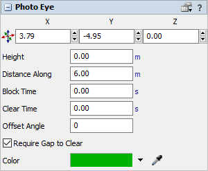
The following properties are on the Photo Eye panel:
Position
Defines the X, Y, and Z position of photo eye.
Height
Defines the height of the photo eye.
Distance Along
Defines how far along the photo eye's conveyor the photo eye is positioned. Changing this value will update the Position.
Block Time
The amount of time a photo eye must be covered before it will change from a blocking state to a blocked state.
Clear Time
The amount of time a photo eye must be clear from items before changing from a clearing state to a cleared state.
Standard Conveyor Properties
The following properties are only applicable for photo eyes attached to standard conveyors (not mass flow conveyors).
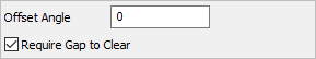
Offset Angle
The offset angle by which the photo eye beam crosses the conveyor plane. If 0, the beam crosses straight across the conveyor.
Require Gap to Clear
If checked (default), there must be a gap between items in order to clear the photo eye. You might uncheck this box if you want the On Clear trigger to fire on every item, no matter the spacing between items.
Mass Flow Conveyor Properties
The following properties are only applicable for photo eyes attached to mass flow conveyors (not standard conveyors).
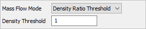
Mass Flow Mode
Defines the method for calculating whether the photo eye is "covered" on a mass flow conveyor. The following options are available.
- Density Ratio Threshold - The photo eye will block/clear when the density of flow units in front of the photo eye crosses a defined threshold. This threshold is expressed as a ratio of the maximum possible density for the flow unit.
- Speed Threshold - The photo eye will block/clear when the speed of flow units in front of the photo eye crosses a defined speed threshold.
Density Threshold
Defines the ratio of the maximum flow unit density that will trigger the blocking/ clearing of the photo. The value should be between 0 and 1. The value 0 means nothing is in front of the photo eye, and 1 means the conveyor is at full capacity in front of the photo eye.
Speed Threshold
Defines the speed threshold of flow units in front of the photo eye that will trigger blocking/clearing.
Color
Defines the photo eye's color. This is the color displayed when the photo eye is in the "cleared" state. The colors for the "blocking", "blocked", and "clearing" states are defined on the properties of the Conveyor System.