Emulation
Overview and Key Concepts
The Emulation tool creates a link between FlexSim and external PLCs or clients/servers that communicate with PLCs. This tool can create multiple connections and define variables for each of those connections. This tool supports multiple protocols, including OPC UA, OPC DA, and Modbus.
The Emulation tool is accessed from the Toolbox.
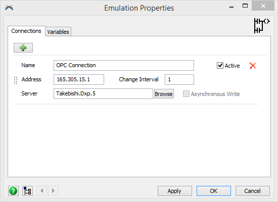
The Connections Tab
The Connections tab has the following properties:
 - Adds a new connection.
 - Removes the connection.
The following five connection types are available:
| Connection | Description |
|---|---|
| Allen-Bradley | A connection to a local or remote OPC server using the Data Access (DA) protocol. |
| Modbus RTU | A connection to a modbus slave or master using a serial (RS-232 or RS-485) port. |
| Modbus TCP/IPv4 | A connection to a modbus client or server over ethernet using TCP/IPv4. |
| Modbus TCP/IPv6 | A connection to a modbus client or server over ethernet using TCP/IPv6. |
| OPC DA | A connection to a local or remote OPC server using the Data Access (DA) protocol. |
| OPC UA | A connection to a local or remote OPC server using the UA (unified architecture) protocol. |
Each connection's properties will be explained below.
Allen-Bradley
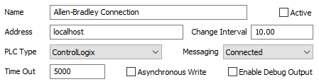
Allen-Bradley connections can be real, meaning FlexSim will communicate through a physical ethernet port on the computer, or they can be virtual, meaning a software program emulates a TCP connection.
- Name - The name of the connection. Used for identifying the connection in FlexSim.
- Active - If checked, a connection will be created to connect FlexSim to an Allen-Bradley PLC. This occurs when the model starts running.
- Address - The ip address of the connection. Use localhost to create a connection with an emulated PLC on this computer or specify the ip address in the form of 190.123.10.1.
- Change Interval - The time interval, in model time units, for FlexSim to poll the PLC for changes.
- PLC Type - The type, or family, of PLC this connection will be connected to. The correct PLC type needs to be specified in order for the connection to work properly.
- Messaging - This option is only available for certain PLC Types. When available, there are two options, Connected and Unconnected. Connected messaging causes FlexSim and the PLC to create an explicit connection where multiple messages can be communicated over a period of time. Unconnected messages are sent from FlexSim to the PLC as single requests.
- Time Out - The time interval, in milliseconds, that FlexSim will use when reading or writing values to the PLC. A time out failure will
- Asynchronous Write - If checked, writing data to the PLC will cause FlexSim to wait until the write operation is complete before continuing execution.
- Enable Debug Output - When checked, FlexSim will output information to the system console as it communicates with the PLC.
Modbus RTU
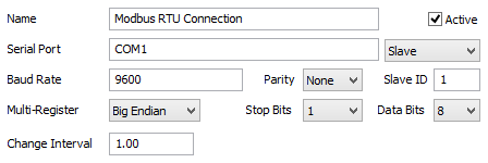
Modbus RTU connections can be real, meaning FlexSim will communicate through a physical serial port on the computer, or they can be virtual, meaning a software program emulates a serial port.
- Name - The name of the connection. Used for identifying the connection in FlexSim.
- Active - If checked, a connection will be created to connect FlexSim to the Modbus Slave or Master through a serial port (virtual or real). This occurs on model reset for slave connections and when the model starts running for master connections.
- Serial Port - The serial port to create the connection on.
- Slave / Master - Specify if the connection is a Slave or Master. Slave connections allow other modbus devices/applications to connect to FlexSim.
- Baud Rate - The baud rate of the connection. The baud rate defines the number of signaling events across the transmission per time.
- Parity - Specify if the connection has a parity. This is a method for detecting errors in transmissions.
- Slave ID - Define the Slave ID of the connection.
- Multi-Register - Specify the endianness of the connection or the order of byte transmission.
- Stop Bits - Specify the number of stop bits or bits at the end of each character in the transmission.
- Data Bits - Specify the number of data bits each character in the transmission can be.
- Change Interval - The time interval, in model time units, for FlexSim to poll the slave for changes. This is only available for master connections.
Modbus TCP/IPv4 and IPv6
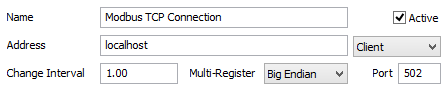
The properties for IPv4 and IPv6 are identical. The only change is in which protocol is used in setting up the connection. Modbus TCP connections can be real, meaning FlexSim will communicate through a physical ethernet port on the computer, or they can be virtual, meaning a software program emulates a TCP connection.
- Name - The name of the connection. Used for identifying the connection in FlexSim.
- Active - If checked, a connection will be created to connect FlexSim to the Modbus Client or Server through an ethernet port. This occurs on model reset for server connections and when the model starts running for client connections.
- Address - The ip address of the connection. Use localhost to create a connection with a virtual client or server or specify the ip address in the form of 190.123.10.1.
- Type - Specify if the connection is a Client or Server. Server connections allow other modbus devices/applications to connect to FlexSim.
- Change Interval - The time interval, in model time units, for FlexSim to poll the server for changes. This is not used for Server connections.
- Multi-Register - Specify the endianness of the connection or the order of byte transmission.
- Port - The port of the connection.
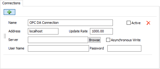
OPC DA
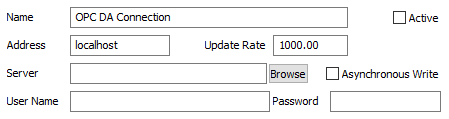
OPC DA connections can be real, meaning FlexSim will communicate through a physical ethernet port on the computer, or they can be virtual, meaning a software program emulates a TCP connection.
- Name - The name of the connection. Used for identifying the connection in FlexSim.
- Active - If checked, a connection will be created to connect FlexSim to an OPC server. This occurs when the model starts running.
- Address - The ip address of the connection. Use localhost to create a connection with a server on this computer or specify the ip address in the form of 190.123.10.1.
- Update Rate - The time interval, in model time units, for FlexSim to poll the server for changes.
- Server - The server to connect to.
- Browse - Click the browse button to display a list of possible servers to connect to at the defined address.
- Asynchronous Write - If checked, writing data to the server will cause FlexSim to wait until the write operation is complete before continuing execution.
- User Name - Used for server authentication if a user name is required to connect to the OPC server.
- Password - Used for server authentication if a password is required to connect to the OPC server.
OPC UA
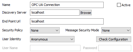
OPC UA connections can be real, meaning FlexSim will communicate through a physical ethernet port on the computer, or they can be virtual, meaning a software program emulates a TCP connection.
- Name - The name of the connection. Used for identifying the connection in FlexSim.
- Active - If checked, a connection will be created to connect FlexSim to an OPC server. This occurs when the model starts running.
- Discovery Server - The ip address of the discovery server. Use localhost to discover servers on this computer, or specify the ip address in the form of 190.123.10.1. Use a suffix such as :51510 to define a non-default TCP port number to communicate over. Once basic values are entered, you can press the Browse button to browse for specific end point URLs to connect to.
- Enable Debug Output - When checked, FlexSim will output information to the system console as it communicates with the server.
- End Point URL - The specific URL defining the server and protocol to connect to. You can auto-fill this field using the Browse button.
- Security Policy - Defines the set of security algorithms and key length
to use when communicating with the server.
- None - No security is applied.
- Basic128Rsa15 - Uses an Aes 128 symmetric encryption algorithm, a SHA1 key hash, and RSA-PKCS15 asymmetric signature algorithm. Note that this policy is no longer considered secure, since SHA-1 was broken in 2017.
- Basic256 - Uses an Aes 256 symmetric encryption algorithm, a SHA1 key hash, and RSA-PKCS15 asymmetric signature algorithm. Note that this policy is no longer considered secure, since SHA-1 was broken in 2017.
- Basic256Sha256 - Uses an Aes 256 symmetric encryption algorithm, a SHA2-256 key hash, and RSA-PKCS15 asymmetric signature algorithm.
- Message Security Mode - Defines the message security mode.
- None - No security is applied.
- Sign - Messages are signed but not encrypted.
- Sign&Encrypt - Messages are signed and encrypted.
- User Identity - Define how, or if, the client user will be identified.
The following options are available:
- Anonymous - No authentication will be used.
- User Name - Specify the user name and password to authenticate with the server.
- Certificate - Use this option if you have a server generated certificate that has been downloaded to the computer running FlexSim.
- Check Configuration - Press this button to check that the entered settings correctly connect to the target UA server.
- Cerificate Path - The file path to the certificate.
- Private Key - The private key associated with the specified certificate.
- User Name - The user name to authenticate with the server.
- Password - The password of the certificate or the user.
The Variables Tab
The Variables tab has the following properties:
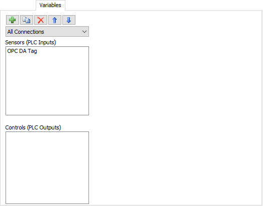
Filters
There are three ways of filtering the Variables List:
- Connections - Only display connections of this type.
- Variables - This can be either local variables, which are variables created using the Emulation tool window, or it can display process flow variables that are dynamically created.
- Variable Types - Only display variables of this type.
| Icon | Description |
|---|---|
|
Adds a variable. |
 |
Duplicates the selected variable. |
|
Removes the selected variable. |
 |
Moves the selected variable up in the list. |
 |
Moves the selected variable down in the list. |
Variables List
Displays a list of variables.
There are three types of variables that can be added, Sensors (PLC Inputs), Controls (PLC Outputs) and Data.
Sensors (PLC Inputs)
Sensors are used to write data to the PLC, server or data variable. If you read from a sensor, the value returned will be the local value stored in FlexSim. If the sensor's connection is active, then changing its value will cause that value to be written to the PLC or server. If the connection is inactive, the value will only be changed locally.
Controls (PLC Outputs)
Controls are used to read data from the PLC, server or data variable. A control can only be changed if the control's connection is inactive. This allows your internal ladder logic to act as the PLC and make changes to controls which can start/stop motors, etc. If you attempt to change a control's value when its connection is active, an exception will be thrown.
When you read from a control, the returned value depends on how the control is setup. If the control is set to Subscribe to Changes or Poll for External Changes (depending on the connection type), the server will notify FlexSim of the changed value (subscribing) or FlexSim will ask for changes using events (polling). If you later try and read the value from these controls, the returned value will be the cached value from the last time FlexSim read the value. If Subscribe to Changes or Poll for External Changes is not checked, reading a control's value will reach out to the PLC or server and read the value synchronously (FlexSim will wait until it receives the value back before the simulation will continue) or asynchronously.
Data
Some connection types, like the Allen-Bradley Connection, have an additional data variable type that pulls data from the server/PLC and then links to sensor and control type variables. These variables are not associated with an object in the model.
The properties of these variables are described below.
Allen-Bradley Tag
Allen-Bradley tags communicate directly with the PLC to read and write data. Allen-Bradley controls and sensors are then linked to a tag where they will get and set values of the tag. This allows you to pull in large amounts of data from the PLC in a single network request rather than one request per variable. A tag can point to a single element or multiple elements. When linked to multiple elements, FlexSim will treat the tag data as an array.
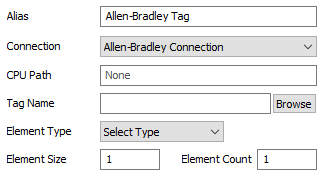
- Alias - The name of the variable. Used for identifying the variable in FlexSim.
- Connection - The connection this variable is associated with.
- CPU Path - For PLCs that require additional routing, this is the path to the CPU that the tag will communicate with. For example, 1, 0.
- Tag Name - The name of the tag on the PLC. This must be the full name of the tag. If accessing a single element from an array, specify the element using TestBigTag[10,42]. Click on the Browse button to display a list of the PLC's available tags.
- Element Type - Defines the data type of each element in the tag.
- Element Size - The data size of each element in bytes.
- Element Count - The number of elements for the tag.
Allen-Bradley Variable
Properties for Allen-Bradley Variables are very similar between the Sensor and Control. These properties are described below.
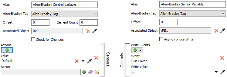
- Alias - The name of the variable. Used for identifying the variable in FlexSim.
- Allen-Bradley Tag - The Allen-Bradley tag this variable is associated with.
- Offset - The first element (0 based) in the Allen-Bradley Tag to start reading from. For example, if the tag's value is [3, 5, 6, 9] and offset is set to 2, the control value will start at 6.
- Element Count - For controls only. This is the number of elements to read from the Allen-Bradley Tag from the Offset. For element counts great than 1, the value will be an array.
- Associated Object - Links this variable with an object in the model.
The associated object defines which Write Events are available
for sensors. In the pick options for Write Events and
Actions,
currentis the associated object. - Asynchronous Write - For sensors only. this option is only available if the connection is not set to use Asynchronous Write. If unchecked, FlexSim will wait until the write operation is complete before continuing execution. Otherwise FlexSim will continue running and not wait for the write operation to finish.
- Write Events - If the sensor has an associated object, events on
that object can be listened to. Click on the
to add a new event.
- Event - The event to listen to.
- Write Value - The value to write to the sensor (and PLC if the connection is active).
- Check for Changes - If checked, the linked Allen-Bradley Tag will be set to poll the PLC for changes to the tag. If the control variable's data has been changed, the tag will cause the variable's value to be updated.
- Actions - When checking for changes, a FlexSim event will be
created based upon the connection's Change Interval. When the event
fires it will read values from the PLC. If the control's value has changed, the control's
actions will be evaluated. Each action is evaluated from the top down until the new value matches
the Value field or it hits a Default. The
Action will then be fired and no further actions will be tested.
Click on the to add a new action.
- Value - The value to match.
- Action - Actions to take when the new value matches the Value.
Modbus Register
Properties for Modbus Register variables are very similar between the Sensor and Control. These properties are described below.
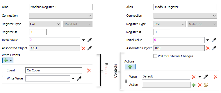
- Alias - The name of the variable. Used for identifying the variable in FlexSim.
- Connection - The connection this variable is associated with.
- Register Type - The type of register. This can be Coil, Discrete Input, Holding Register, Input Register. For holding and Input register, the data type drop down button defines what data type the register is.
- Register # - Define the register's address (0 - 9999).
- Initial Value - The initial value of the register. This is only available for Server or Slave type connections that store their own data.
- Associated Object - Links this variable with an object in the model.
The associated object defines which Write Events are available
for sensors. In the pick options for Write Events and
Actions,
currentis the associated object. - Write Events - If the sensor has an associated object, events on
that object can be listened to. Click on the
to add a new event.
- Event - The event to listen to.
- Write Value - The value to write to the sensor (and server if the connection is active).
- Poll for External Changes - Polls the slave or server for changes to the control's value. This is only available for master and client type connections.
- Actions - When polling for changes, a FlexSim event will be
created based upon the connection's Change Interval. When the event
fires it will read values from the server. If the control's value has changed, the control's
actions will be evaluated. Each action is evaluated from the top down until the new value matches
the Value field or it hits a Default. The
Action will then be fired and no further actions will be tested.
Click on the to add a new action.
- Value - The value to match.
- Action - Actions to take when the new value matches the Value.
OPC DA Tag
Properties for OPC Tag variables are very similar between the Sensor and Control. These properties are described below.
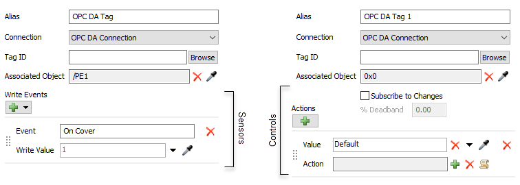
- Alias - The name of the variable. Used for identifying the variable in FlexSim.
- Connection - The connection this variable is associated with.
- Tag ID - The path of the tag on the server. Click on the Browse button to display a list of the server's available tags.
- Associated Object - Links this variable with an object in the model.
The associated object defines which Write Events are available
for sensors. In the pick options for Write Events and
Actions,
currentis the associated object. - Write Events - If the sensor has an associated object, events on
that object can be listened to. Click on the
to add a new event.
- Event - The event to listen to.
- Write Value - The value to write to the sensor (and server if the connection is active).
- Subscribe to Changes - Subscribes to changes on the server. FlexSim will be notified when the value changes.
- % Deadband - When subscribing to analog changes, the % deadband can filter out small changes to the control's value (noise).
- Actions - When subscribing to changes, a change notification will
be sent to FlexSim when the control's value changes. Actions allow you to define what happens with that
notification based upon the new value. Each action is evaluated from the top down until the new value
matches the Value field or it hits a Default. The
Action will then be fired and no further actions will be tested.
Click on the to add a new action.
- Value - The value to match.
- Action - Actions to take when the new value matches the Value.
OPC UA Variable
Properties for OPC UA Variables are very similar between the Sensor and Control. These properties are described below.
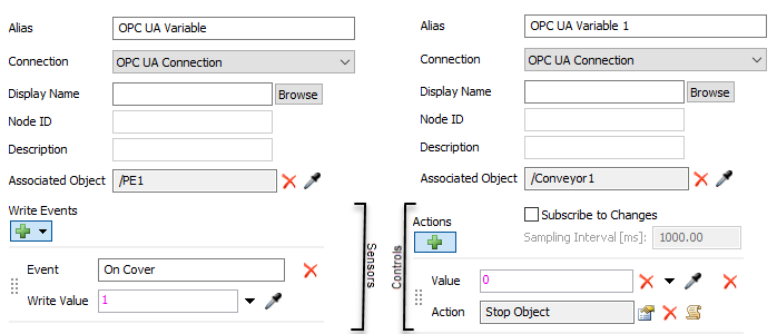
- Alias - The name of the variable. Used for identifying the variable in FlexSim.
- Connection - The connection this variable is associated with.
- Display Name - The path of the variable on the server. Click on the Browse button to display and select from a list of the server's available tags.
- Node ID - Displays the UA id string of the variable.
- Description - Displays the UA description of the variable.
- Associated Object - Links this variable with an object in the model.
The associated object defines which Write Events are available
for sensors. In the pick options for Write Events and
Actions,
currentis the associated object. - Write Events - If the sensor has an associated object, events on
that object can be listened to. Click on the
to add a new event.
- Event - The event to listen to.
- Write Value - The value to write to the sensor (and server if the connection is active).
- Subscribe to Changes - Subscribes to changes on the server. FlexSim will be notified when the value changes.
- Sampling Interval [ms] - Defines how often the variable will be sampled from the serve to detect changes to the variable.
- Actions - When subscribing to changes, a change notification will
be sent to FlexSim when the control's value changes. Actions allow you to define what happens with that
notification based upon the new value. Each action is evaluated from the top down until the new value
matches the Value field or it hits a Default. The
Action will then be fired and no further actions will be tested.
Click on the to add a new action.
- Value - The value to match.
- Action - Actions to take when the new value matches the Value.