Working With Travel Networks
Introduction to Travel Networks
You can use the Travel Network objects to define the specific paths that task executers can use to get from one location to another in the simulation model. Before reading this topic, you should make sure you are familiar with the concepts discussed in Key Concepts About Travel. This topic will provide a high-level overview of how travel networks work.
The rest of this topic will provide instructions about how to do the various tasks needed to build a travel network.
Adding and Connecting Network Nodes
The first step in building any travel network is to add network nodes to your model and connect them together to form travel paths:
- With the Library open, under the Travel Network group, drag a NetworkNode into your 3D model. It will appear visually like a square point in your model.
- Place additional network nodes as needed in the model. Generally, it's best to place
nodes:
- Next to the fixed resources to which task executers will travel
- Next to the model reset position of task executers
- At key travel junctures, such as the beginning and end of a hallway
- You can connect network nodes together using the same method you'd use to create
input/output port connections (A-connects) between fixed resources. Click the
Connect Objects button
 on the toolbar to
open a menu. Select Connect Objects from the menu to turn
on connection mode.
on the toolbar to
open a menu. Select Connect Objects from the menu to turn
on connection mode. - When you are in connection mode, your mouse pointer will change to a plus sign with
a chain link symbol next to it:

- Once you are in connection mode, click the first network node you want to connect. You will notice as you move your mouse that a yellow line will appear between the network node you clicked and your cursor.
- Click a second network node to create a travel path between the two nodes.
- You will still be in connection mode even after you connect two network nodes together. If you need to exit connection mode, press the Esc key or right-click a blank area in the model. Otherwise, you can continue connecting network nodes together if needed.

Creating Curved Paths
To create a curved travel path:
- Create a connection between two nodes using the method outlined in the previous section.
- Right-click the travel path to open a menu. Select Curved.
- Two spline points will appear on the path. Drag these spline points to create an appropriate curve.
Deleting Network Nodes and Connections
When you delete a network node, it will also remove any paths that are connected to it. To delete a network node:
- Click the node in the 3D model.
- Press the Delete key.
Simply deleting a connection between nodes involves more steps than you might expect. It is similar to deleting port connections, but slightly different. To delete a connection:
- Click the Disconnect Objects menu
 on the toolbar
to open a menu. Select Disconnect Objects from the menu to
turn on disconnection mode.
on the toolbar
to open a menu. Select Disconnect Objects from the menu to
turn on disconnection mode. - When you are in disconnection mode, your mouse cursor will change to a plus sign
with a broken chain link symbol next to it:

- Once you are in disconnection mode, you can remove a connection between two nodes. Click the first node you want to disconnect. You will notice as you move your mouse that a yellow line will appear between the node you clicked and your cursor.
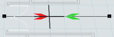
- Click the node to which it is connected. The connection will change to a red arrow.
- While still in disconnection mode, click the second node again, then click the first node to fully delete the path.
- You will still be in disconnection mode even after you remove the connection between two objects. You can continue disconnecting objects together if needed.
Connecting 3D Objects to the Travel Network
After you've created the travel paths, you then need to connect the 3D objects in the model to the travel network.
When you connect a task executer to network node, that node will act as the entry point where the task executer will enter the travel network. You should try to use a network node that is close to the task executer's starting reset position. When a task executer is connected to a network node, it will display a red line between it and the node:
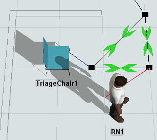
When you connect a fixed resource to the travel network, that node will make it possible for task executers to travel to that location. If you don't connect the fixed resource, it could result in error messages during a simulation run. When a fixed resource is connected to a network node, it will display a blue line between it and the node:
To connect 3D objects to a travel network:
- You can connect fixed resources and task executers to nearby network nodes using the
same method you'd use to connect network nodes together. Click the
Connect Objects button
on the toolbar to
open a menu. Select Connect Objects from the menu to turn
on connection mode.
- When you are in connection mode, your mouse pointer will change to a plus sign with
a chain link symbol next to it:
- Once you are in connection mode, click the network node you want to connect to a 3D object. You will notice as you move your mouse that a yellow line will appear between the network node you clicked and your cursor.
- Click the fixed resource or task executer to create a connection with the node.
Editing Node Properties
How you will edit a network node's properties will depend on which properties you want to edit.
You can right-click a node to open a menu to increase or decrease its draw size.
You can double-click a node to open its properties window. On this window, you can edit the settings for each connection. You can also edit the node's triggers, labels, and general properties---the same as you would for any fixed resource. See the Network Node reference page for a more detailed explanation of each property.
You can also right-click a path to open a menu with some different properties. You can also right-click a directional arrow to open a menu with properties. Try experimenting with some of the options to see what they do.
Editing Network Properties
To edit the properties for the entire network:
- Right-click any network node to open a menu and select Network Properties to open the properties window.
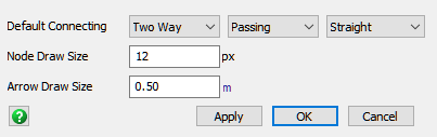
- Make any changes to the network properties as needed. You can set the default connection types and the node or arrow draw size.
Using Traffic Controllers and One-Way Paths
You can add one or more traffic controllers to your model to help prevent collisions on certain paths in your model. A traffic controller can restrict access to a specific path or a set of paths. You will basically use it to define a restricted area that will only let a specific number of task executers in the area at a time. If a task executer tries to enter a restricted area while another traveler is occupying that area, the task executer will wait.
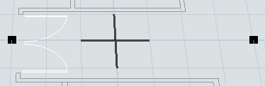
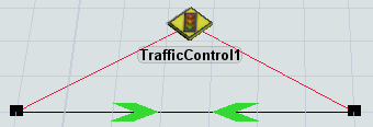
The following image shows an example of a network node system before a traffic controller has been added:
Notice that the operators frequently walk through each other while traveling on the center path.
Now compare the same system in which a traffic controller is connected to the two nodes on the center path:
The operators no longer walk through each other while traveling on the center path. Instead, they wait their turn and enter one at a time.
Notice that they do overlap each other while waiting at a node, though. One way to solve this might be to introduce a second center path and changing both paths so that traffic can only flow one direction:
The following sections will explain how to add traffic controllers and create one-way paths.
Adding and Connecting Traffic Controllers
To add and connect a traffic controller:
- In the Library under Travel Networks, drag a TrafficControl object into the 3D model, placing it near the nodes you want to control.
- You can connect a traffic controller to nearby network nodes using the same method
you'd use to connect network nodes together. Click the Connect
Objects button
on the toolbar to
open a menu. Select Connect Objects from the menu to turn
on connection mode.
- When you are in connection mode, your mouse pointer will change to a plus sign with
a chain link symbol next to it:
- Once you are in connection mode, click the traffic controller. You will notice as you move your mouse that a yellow line will appear between the traffic controller you clicked and your cursor.
- Click a network node to connect it to the traffic controller. When a traffic controller is connected, you'll see a red line between the traffic controller and the node.
Creating One-Way Paths
The color of the directional arrows on a network path indicate the direction of travel and whether the network path allows faster task executers to pass slower or stopped task executers:
| Arrow Color | Meaning |
|---|---|
 |
Travel can occur in this direction and passing is allowed |
 |
Travel can occur in this direction but passing is not allowed |
 |
Travel cannot occur in this direction |
To create a one-way path:
- Click the Disconnect Objects menu
on the toolbar
to open a menu. Select Disconnect Objects from the menu to
turn on disconnection mode.
- When you are in disconnection mode, your mouse cursor will change to a plus sign
with a broken chain link symbol next to it:
- Once you are in disconnection mode, you can remove a connection between two nodes. Click the first node you want to disconnect. You will notice as you move your mouse that a yellow line will appear between the node you clicked and your cursor.
- Click the node to which it is connected. The connection will change to a red arrow.
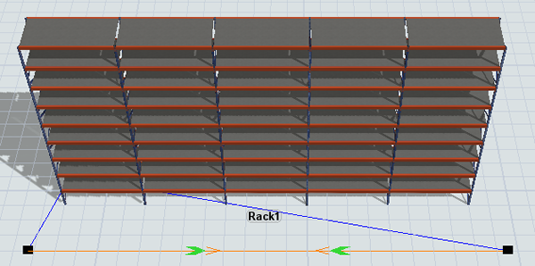
Creating Alternate Exits
Sometimes you might want to connect fixed resources to more than one network node---especially if you've got a particularly long fixed resource such as a rack or a waiting line. When working with a fixed resource connected to two network nodes, you sometimes get strange behavior where a task executer doesn't travel on the most efficient path. This behavior is caused by the logic that controls how network nodes interact with fixed resources.
By default, a task executer will exit a location using the same network node that it used to enter a location. You can see this behavior in the following image:

In this example, both queues are assigning transport tasks to a transporter. First one queue assigns a transport task and then the next queue assigns it, alternating in an almost round robin fashion. Notice how it would be more efficient if the task executer exited using the opposite network node that it entered from. Instead, the transporter backtracks to the network node that it entered from before traveling to the other queue.
You can fix this behavior by adding alternate exits to the path. Creating an alternate exit makes it so that the task executer can exit from either of the network nodes connected to a fixed resource, depending on which is more efficient:
Notice how the transporter can now use either node as an exit.
To create an alternate exit:
- Create a connection between two nodes. Also, don't forget to check that the nodes are connected to the fixed resource.
- Press and hold the D key to enter alternate exit creation mode.
- When you are in connection mode, your mouse pointer will change to a plus sign with
a chain link symbol next to it:
- Once you are in connection mode, click the first network node you want to connect. You will notice as you move your mouse that a yellow line will appear between the network node you clicked and your cursor.
- Click a second network node to create an alternate exit connection between the two nodes. The path will turn orange to indicate that the connection allows alternate exits.
Turning Travel Network Visibility On or Off
After you've built your travel networks and validated that they work correctly, you might want to turn off the travel network's visibility to reduce the model's visual clutter. To turn off travel network visibility:
- Pick a network node that is located in a position where you will be likely to remember it. Right-click the node to open a menu. Point to Network View Mode and select None.
- Notice that all of the other network nodes and paths will become invisible except for the network node you used to change the network view mode.
- To turn the visibility back on, right-click the same node that you used to turn the visibility off. Point to Network View Mode and select Show All.
Using Travel Networks With People Objects
You can use FlexSim's people-based 3D objects and process flow activities to simulate business systems that are based around the flow of people rather than items, such as customer service centers or health care facilities. The customers or patients that flow through these kinds of simulation models are a special kind of task executer. As such, you can control their travel behavior the same way you would any other task executer. However, one difference is that these customers or patients aren't created until the simulation runs, so you can't connect them to the travel network directly.
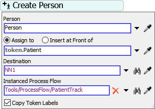
The way to fix this problem is to create the person at one of the network nodes rather than a location:
- At some point while building a people-based model, you'll use a Create Person activity in your process flow. Click this activity to select it.
- In Quick Properties next to the Destination box, click
the Sampler button
 to enter sampling mode.
 - In the 3D model, click one of the network nodes to open a menu. Select the network node's name from the menu. (Generally, the name starts with NN and is followed by a number.)
Virtual Distances
Using travel networks, you can create virtual distances between two nodes. A virtual distance is when you make the distance between nodes longer or shorter than the actual distance in model units. Virtual distances can be helpful if you want to simulate a task executer traveling a long distance from one point to another but you don't want to actually put those two nodes that far apart in your model.
The following example shows an operator traveling on a path before the virtual distance has been applied:
On the uppermost path, the distance from the left node to the right node is 7 model units.
The following image shows an operator traveling a virtual distance of 50 model units on the uppermost path:
Notice that the operator now walks slower while on the uppermost path to simulate the virtual distance between the two points. Also notice that the virtual distance only applies in one direction. To fix that, you'd have to apply the virtual distance to the connection going both ways.
To create a virtual distance between two points:
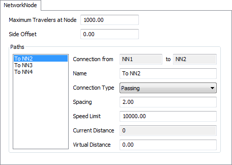
- Double-click one of the nodes on either end of the path that you want to use to create a virtual distance.
- On the NetworkNode tab in the Paths group, select the path connection you want to change to a virtual distance.
- Note that the Current Distance box displays the actual distance between the two nodes in model units.
- In the Virtual Distance box, type the distance in model units that you want FlexSim to treat as the virtual distance.
- Click the OK button to save the changes and close the properties window.
- If you want to apply the virtual distance going in the opposite direction on the path, double-click the network node on the opposite end of the path and repeat the previous steps.
Travel Offsets
Be aware that for statistical purposes, once a task executer has reached a network node, FlexSim will consider the travel task to be complete. After that point, you might see a task executer continue traveling if it has to walk closer to a fixed resource. That travel time is called a travel offset, while the animation is appears to be traveling even though FlexSim no longer considers the task executer to be traveling.
Just keep in mind that the travel offset period will not count as traveling for statistical purposes. You could compensate for this by creating a custom statistics collector or a milestone collector. See Key Concepts About Getting Data for more information.