Task 1.4 - Power and Free Systems
Task Overview
In this tutorial task, you'll convert the simulation model into a power and free conveyor system. Power and free conveyor systems typically use a series of overhead trolleys that are propelled by dogs that continually move through the conveyor system. They are ideal for moving any type of load over large distances, differing elevation levels, and complex paths.
In this task, you'll learn how to make your conveyor system look and function more like a power and free system. When you're finished, your final simulation model should look similar to the following image:
Cautions About Simulating Power and Free Systems
The simulation you build in this lesson will not explicitly simulate the carriers in a power and free system. Carriers are the objects that latch onto the dogs of the power and free chain. Usually there are a fixed number of carriers in a system, and they loop around within it. The items that need to be moved in the system are loaded onto available carriers, which then take them to their desired destination.
Admittedly, not simulating the carriers in a power and free system can be justifiably considered a critical oversimplification. Varying the total number of carriers in a system, and their proper distribution, can have huge impacts on overall throughput. However, since the purpose of this tutorial is just to learn how to use FlexSim's power and free features, carriers will be left out. This simulation model will assume that carriers are available to pick up items when they are needed.
In FlexSim, enabling power and free operation for a given conveyor or conveyors essentially causes them to enforce fixed interval movement. This means that items will only move at points on the conveyor where simulated dogs are located. If you want to simulate carriers, simply make the items that are moved directly into the conveyor system be the carriers. Create a fixed number that enter when the simulation starts, and then loop them around the system. Then move other items (the "loads") into and out of those carriers at various points in the system, simulating the actual movement of value-added material through the system.
Step 1 Update the 3D Model
Power and free conveyor systems usually suspend large items from the underside of the conveyor. For that reason, you'll raise the height of the entire conveyor system in this step. You'll also remove the merge controller and add the conveyor motor object to the model. One of the advantages of power and free conveyor systems is they can usually be controlled with a single motor, so this single motor will power all the conveyors.
To make these changes to the 3D model:
- In the Toolbox, under the Process Flow group, right-click the Gap-Optimizing Merge Controller process flow to open a menu. Select Delete to delete the process flow.
- In the 3D model, delete the following objects:
- The merge controller
- The gapping conveyor
- The join conveyor that connected the merging conveyor to the gapping conveyor
- The decision point on the merging conveyor
- Add four Decision Points to the center of each slug-building conveyor.
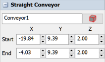
- Click any conveyor to select it. In Quick Properties, change the
Z property (which affects the height) to
2.00for both the Start and End of the conveyor. - Repeat the previous step for all the conveyors in the model.
- In the Library under Conveyors, drag a Motor to the model and place it anywhere.
- Create port connections (A-connects) from the Motor to every conveyor in the system, including the four curved conveyors.
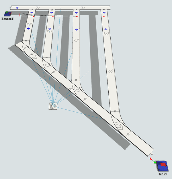
When you're finished, your model should look approximately like the following image:
Step 2 Create a Global Decision Point Type
In this simulation model, you want to divert the flow items to a specific conveyor for painting. Each flow item will be painted a specific color based on its item type.
Since the conveyor already sends items to a specific conveyor based on the value of the type label, you don't need to program that logic. Instead, you'll set the decision points in the middle of each conveyor to delay the item for 10 simulation seconds. At the end of this time, the flow item will change color, representing its paint job.
- In the Toolbox, click the Add button
 to open a menu. Point to
Conveyor System, then click Decision
Point Type to open the Decision Point Type Properties.
to open a menu. Point to
Conveyor System, then click Decision
Point Type to open the Decision Point Type Properties. - Rename this decision point type
PaintStationin the top box. - Next to the On Arrival box, click the
Add button
 to open a menu. Point to Stop/Resume, then
Stop Item and Delay.
to open a menu. Point to Stop/Resume, then
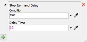
Stop Item and Delay. - With the Stop Item and Delay picklist options open, in the
Delay box type
10. - In the Triggers group, click the
Add button
to open a menu. Select On Continue.
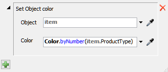
- Next to the On Continue box, click the
Add button
to open a menu. Point to Data, then Set
Object Color.
- With the Set Object Color picklist options open, in the
Color box type
Color.byNumber(item.ProductType). - Click the OK button and confirm that the new Decision Point Type is listed in the Toolbox.
- Click the Decision Point that is in the middle of the ItemType1 conveyor to select it. (Not the Decision Point that is at the beginning of the conveyor.)
- In Quick Properties, open the Decision Point Type menu and select PaintStation to assign this decision point to the new global type you created.
- Repeat steps 8-9 for the other decision points that are in the middle of the diverting conveyors.
Consider saving your simulation model.
Step 3 Create a Power and Free Conveyor Type
Power and free conveyors usually have a thin width and occasionally are painted in bright colors. They also typically move at speeds that are slower than other conveyors because they tend to carry such heavy loads. In this step, you'll create a global conveyor type that has these properties and apply it to the conveyors in your system.
To create a power and free conveyor type:
- In the Toolbox, click the Add button
to open a menu. Point to
Conveyor System, then click Conveyor
Type to open the Conveyor Type Properties.
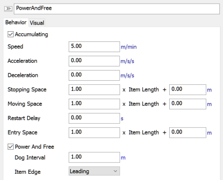
- Rename this conveyor type
PowerAndFreein the top box. - On the Behavior tab, click in the
Speed box and change it to
5.00. Then click the m/s link next to this box to open two menus. Click the second menu and change it to meters per minute. - Check the Power and Free checkbox. Leave the other settings at their default.
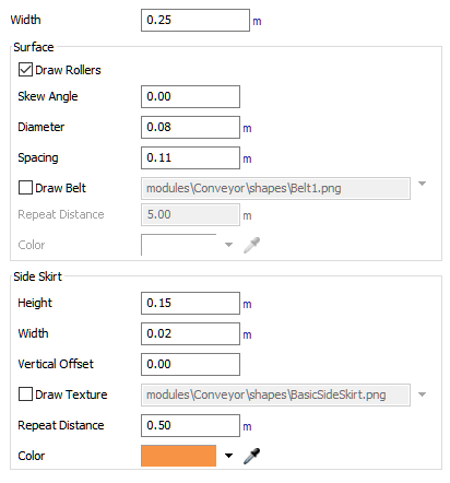
- On the Visual tab in the
Width box, type
0.25. - In the Side Skirt group, click the arrow next to the Color box and select the orange color.
- Click the OK button and confirm that the new Conveyor Type is listed in the Toolbox.
- Click any conveyor in the 3D model to select it.
- In Quick Properties, open the Conveyor Type menu and select PowerAndFree to assign this conveyor to the new global type you created.
- Repeat steps 8-9 for the other conveyors.
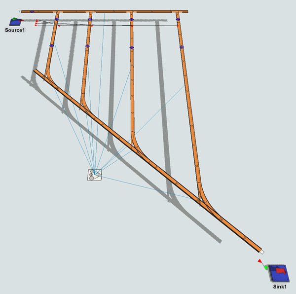
When you're finished, your model should look approximately like the following image:
Step 4 Change Flow Item Properties and Movement
Most power and free conveyor systems are designed to carry heavy loads. In this step, you'll create a large flow item that will travel along the power and free conveyor system. Then you'll set the Source to add this type of flow item to the conveyor system. Since power and free systems tend to operate more slowly, you'll also set the source to release the flow items less frequently.
Lastly, you'll set the first decision point on the conveyor to translate this new flow item. The word translate in this context means to change the position of the flow item relative to the conveyor. In this case, you'll set the decision point to translate the flow item so that it travels underneath the conveyor, which is typical for power and free systems.
To make these modifications to the model:
- In the Toolbox, click the arrow
 next to the FlowItem Bin to expand the list of flow
items.
next to the FlowItem Bin to expand the list of flow
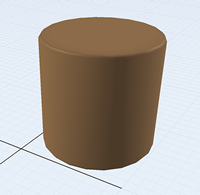
items. - Double-click the Cylinder flow item to open it in the Flow Item Bin.
- In Quick Properties, change the X-size
 to
to 1. Change the Y-size and Z-size to1as well. - Click the Model tab to return to the 3D Model.
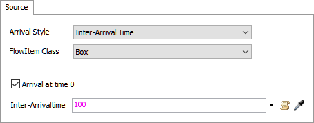
- Double-click the Source to open its properties window.
- On the Source tab, open the FlowItem Class menu and select Cylinder.
- Check the Arrival at time 0 checkbox.
- In the Inter-arrival Time box, type
100. - On the Triggers tab, click the
Add button
to open a menu. Select On Creation.
- Next to the On Creation trigger, click the
Edit Properties button
 .
. - Next to the Set Object Color, click the
Remove button
 to delete this picklist.
 - Press OK to save the changes.
- Double-click the first Decision Point on the first conveyor (the one closest to the source) to open its properties window.
- On the Decision Point tab next to the
On Arrival trigger, click the Edit
Properties button to
open the picklist options.
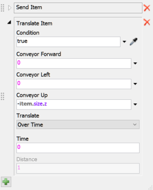
- Underneath the Send Item box, click the
Add button
to open a menu. Point to Movement, then select
Translate Item.
- In the Conveyor Up box, type
-item.size.z. - Click the Translate menu and select Over Time.
- In the Time box, type
0. - Press OK to save the changes.
Run the simulation model and watch as large flow items slowly travel along the power and free conveyor to a painting station based on their item Type. Notice that lines move across each conveyor system in sync with the motor. These lines represent the movement of dogs throughout the power and free system.
Most power and free conveyors move at slow speeds because of the heavy loads they transport. For that reason, be aware that the following image is shown at a faster simulation run speed:
Conclusion
This concludes the conveyor tutorial. For a deeper discussion of how to use conveyors in FlexSim, consider reading the chapter about conveyors entitled Connecting 3D Object Flows.