Conveyor Types
Overview and Key Concepts
Conveyor types are global settings that you can import to any straight or curved conveyor object in your simulation model. The Conveyor Types properties window has two different tabs with various properties. These properties will be explained in the following sections.
The Behavior Tab
The Behavior tab has the following properties:
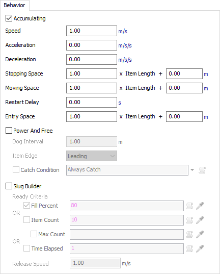
Accumulating
If this box is checked, items will accumulate on the conveyor, meaning they will collect together along the conveyor, similar to a roller conveyor. If this check box is cleared, items will move in lock-step with each other, like on a belt conveyor. By default, this box is checked.
Speed
The default speed of the conveyor.
Acceleration
The conveyor's rate of speed change as it moves when it first starts or when it changes from a slower speed to a faster speed.
Deceleration
The conveyor's speed as it slows down to a stop or when it changes from a faster speed to a slower speed.
Stopping Space
The minimum amount of space between items while they travel along the conveyor of while they are accumulating. If the space between items is less than the specified space, the item will stop moving.
Moving Space
If items are stopped along a conveyor, this is the amount of space needed between items before they can resume movement.
Restart Delay
If you define a non-zero restart delay time, after items are stopped on a conveyor, this additional time will be applied before starting the items again after their move space has been cleared.
Entry Space
The amount of space that must be clear before an item will enter a conveyor.
Each spacing setting has two different fields, as illustrated in the image below:

The first editable number field, the Length Factor field, allows you to a percentage of space multiplied by the item's length. 1.00 is equivalent to 100%, or in other words the full length of the item. The value 0.5 would be equivalent to 50%, half the item's length. And 2.00 would be equivalent to 200%, twice the item's length.
The second editable number field, the Additional Spacing field, allows you to add an additional amount of space based on the units of measurements you specify.
Using these two fields, you can create a dynamic set of spacing rules that is either relative or absolute to the item's length. The following images show examples and explanations of different spacing settings:
The default of 1.00 x Item Length + 0.00m defines spacing based purely on item length. |
 Defining a spacing value of 1.00 x Item Length + 0.06m adds a gap of 6 centimeters from the trailing edge of one item to the leading edge of the item behind it. |
 A spacing of 0.00 x Item Length + 0.5m defines a 0.5 meter spacing from the leading edge of one item, to the leading edge of the next item, independent of item length. |
Power and Free Settings
The next group of settings is designed for use in simulating Power and Free conveyor systems. In these systems, dogs travel at fixed intervals along a looping chain. These dogs pick up carriers in the system as they pass them. In simulation terms, it is similar to having a moving space greater than stopping space (there is a caterpillar-like accumulation effect), except that the point at which an item can move on the conveyor is defined by the location of the next passing dog, instead of by the space between it and the item ahead of it.
The available settings are:
- Power and Free - If checked, items can only move on the conveyor at fixed intervals, at the points where simulated dogs pass the item's position.
- Dog Interval - The spacing between each dog on the Power and Free chain. If you want to simulate a repeating irregular pattern of gaps between dogs, you can enter in a series of custom numbers separated by commas.
- Item Edge - Defines the associated item edge to be picked up by a dog.
- Catch Condition - Check this box to enable a custom condition defining whether a given dog will "catch" a given item. One example reason for using this feature might be to simulate randomly missed dogs. Another example would be in order to simulate a cross belt sorter with defined "cells". Larger items take up a full cell, while smaller items can fit two on a cell. Here you would define two dogs per cell, and larger items can only catch the even numbered dogs.
Slug Building Settings
The last group of settings allow conveyors to build slugs. Conveyors can build and release slugs as part of a saw-tooth merge.The Slug Building settings are as follows:
- Slug Builder - Enables slug building when checked.
- Ready Criteria - Defines when a slug lane can be
considered ready for release. One or more of three options should be chosen. If any of
the checked items is fulfilled, the slug will be marked as ready for release. The slug
may continue to build while waiting for release. If the conveyor is not connected to a
Merge Controller, it will release slugs as soon as they are ready for release.
- Fill Percent - Select this box and enter a value to define the percentage of the full conveyor length that is required for the slug to be ready for release.
- Item Count - Select this box and enter a value to define the number of items in a slug required to be ready for release.
- Max Count - This only applies if Item Count is also selected. Select this box and enter a value to define the maximum number of items in a slug. If this is defined, the conveyor will release no more than this number of items in a single slug.
- Time Elapsed - Select this box and enter a value to define a maximum elapsed slug-build time. The time starts when the first item is added to the slug. If the slug is still not ready when the timer finishes, the slug will be made ready for release.
- Release Speed - The speed at which a slug will be released.
The Visual Tab
Visual settings mostly define how conveyors look when drawing in render mode. Render mode can be enabled in Conveyor System Properties. The Visual tab has the following properties:
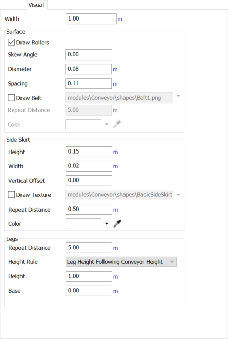
Width
The width of the conveyor.
Surface
The surface pane allows you to define visual properties associated with the convey surface.
Draw Rollers
Check this box to enable the drawing of rollers on the conveyor surface.
Skew Angle
The angle, in degrees, at which the rollers are skewed. If non-zero, items will convey to one side of the conveyor as they travel down it.
Diameter
The diameter to draw rollers when in render mode. Only used in render mode.
Spacing
The distance from the center of one roller to the center of the next roller. Should be greater than Roller Diameter. Only used in render mode.
Draw Belt
Check this box to enable the drawing of a belt on the conveyor surface. Then you can define the texture to be drawn. There are several automatic options, or you can browse for the file.
Repeat Distance
The distance between each repeat of the conveyor belt texture.
Color
The color to apply when drawing the belt texture.
Side Skirt
The side skirt pane allows you to define visual properties associated with drawing the conveyor's side skirts.
Height
The height of the conveyor's side skirt.
Width
The width of the side skirt. Only used in render mode.
Vertical Offset
Defines the position of the side skirt relative to the conveyor plane. This is defined as a ratio of the Side Skirt Height. Usually the value will be between -0.5 and 0.5. For a value of -0.5, the side skirt will extend down from the conveyor plane. For a value of 0.0, the side skirt's center will follow the conveyor plane. For a value of 0.5, the side skirt will extend up from the conveyor plane.
Draw Texture
Check this box to draw a texture for the side skirt, instead of drawing a pre-defined shape. Then you can define what texture to use. There are some pre-defined options, or you can browse for an image.
Repeat Distance
Check this box to define repeat distance associated with the side skirt. This applies both if you are using a side skirt texture, or if you want the conveyor to draw its pre-defined side skirt shape.
Color
Defines the color to apply when drawing the side skirt. When in non-render mode, this applies to bot the side skirt and the conveyor surface.
Legs
The legs pane allows you to define visual properties associated with drawing the conveyor's legs.
Repeat Distance
The distance between each leg of the conveyor. Only used in render mode.
Height Rule
Defines how the height of each leg will be determined. Only used in render mode.
- Leg Height Following Conveyor Height - Legs will be a set height no matter how the conveyor rises or falls. If the conveyor rises, leg bases will rise with it.
- Leg Height from Lowest Point on Conveyor - Leg height is determined from the lowest point on the conveyor. For example, if the conveyor plane goes from z = 1.00 to z = 5.00, and the Leg Height is defined as 1.00, the leg base will be at z = 0.00 all along the conveyor (lowest point (1.0) minus leg height (1.0)).
- Leg Base Relative to Model - Legs will extend to a fixed model z position, defined by the Leg Base, no matter how high the conveyor is.
Height
The conveyor leg height. Only used in render mode when Leg Height Rule equals Leg Height Following Conveyor Height or Leg Height From Lowest Point on Conveyor.
Base
The leg base z-point. Only used in render mode when Leg Height Rule equals Leg Base Relative to Model.