Key Concepts About Emulation
When to Use Emulation
Emulation is a term that refers to the ability to create simulated programmable logic controller (PLC) logic. If you are simulating a system that will eventually use PLCs, you can use emulation to develop and test the PLC logic within FlexSim without needing to create the ladder logic in other software.
Not every simulation project will necessarily benefit from using emulation. The following are the likely scenarios in which you might use FlexSim's emulation tool:
- Designing PLC logic that will be handed off to a different team member who will program the actual ladder logic. As the simulation expert, your expertise might be in designing efficient manufacturing systems, not necessarily in programming PLCs. Using the emulation tool, you can design the ideal logic that the PLCs in your system should use. Then, you can use the emulation tool to communicate how that logic should work to the employee who will program the actual PLC for the real-world system.
- Testing the accuracy of the PLC logic after it has been programmed. After the ladder logic of the PLC has been implemented, you can connect FlexSim to the actual system and determine if the PLC logic has been programmed correctly. As the simulation model runs and gets input from the actual system in real time, you can compare the simulation model with the results from the system to validate that the PLC was programmed correctly.
If these scenarios apply to your simulation project, then emulation might be a useful tool for you.
Overview of an Emulation Project
The process for building an emulation simulation project is shown in the following image:
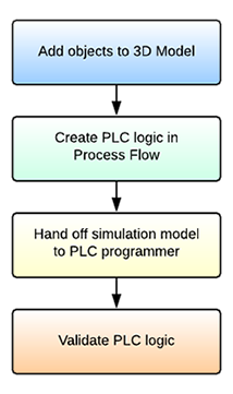
The following sections will explain each phase of the process and link to other relevant topics for more detail.
Add Objects to the 3D Model
Begin by adding objects to your 3D model the way you would with any other simulation project.
Create PLC Logic in Process Flow
Where an emulation project differs from a normal simulation project is the way you'll build the model's logic in process flow. If you want to use emulation in your simulation project, you should integrate PLC-centric logic into your model's process flow early in the model-building process. You'll do this by building your logic in such a way that it resembles the inputs and outputs of a PLC controller.
Hand Off Simulation Model to PLC Programmer
After building the model logic, you should test and validate your simulation model until you feel confident that you've designed an optimal system. At this point, you can then hand off the simulation model to a PLC programmer and explain the model logic to them. Since the process flow will be designed in a PLC-centric way, it should be fairly easy for a PLC programmer to translate the process flow into ladder logic.
Validate PLC Logic
After the PLC has been programmed, you can then use FlexSim to validate that the PLC logic was programmed correctly. You can connect FlexSim directly to the PLC or to the server that the PLC will use. As FlexSim runs and communicates with the PLC, you can compare the results of the simulation model when it was running its internal logic. By comparing the two systems, you'll be able to confirm that the logic is correct or make subtle adjustments to the simulation model or PLC as needed.
Tools for Emulating PLC Logic
You can emulate PLC logic using two different methods in FlexSim. You can add variables and build the logic in the Process Flow tool or you can use the Emulation tool in the Toolbox. In some respects, the tool you choose to use will be a matter of personal preference. However, this guide will generally focus on building emulation in the Process Flow tool because it is good for model documentation and communicates logic in a clear way. Be aware that some of the screenshots in this topic will come from the Emulation tool.
Key Terms
The following are a few terms that are important to understanding the emulation tool in FlexSim:
PLC
PLC is a common abbreviation for programmable logic controller. PLCs are computers dedicated to interacting with machinery in manufacturing systems. These specialized computers generally act as the brains of an automated manufacturing system, connecting the system's inputs and outputs to control the system's overall behavior.
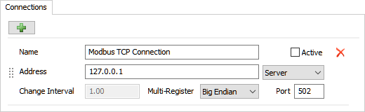
Connections
In the context of FlexSim's emulation tool, the term connections refers to connections between FlexSim's emulation tool and a server or PLC. Currently, FlexSim can connect via OPC and Modbus.
When you're setting up a connection to a server in FlexSim, you can decide whether to make that connection active or inactive. If the connection is active, FlexSim will read and write data directly from an actual server or PLC. If the connection is inactive, it will instead pull data from the theoretical simulation model you created in FlexSim.
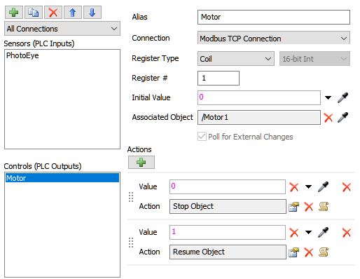
Variables
In this context, the term variable refers to any inputs and outputs that are received or sent by the PLC. FlexSim has two types of variables: sensors (inputs) and controls (outputs).
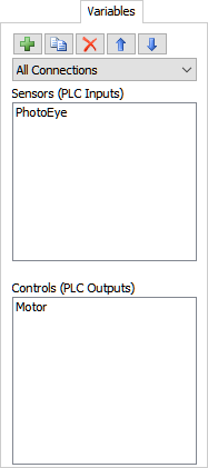
Sensors (PLC Inputs)
Sensors are the inputs to the PLC. Inputs tell the PLC about the manufacturing environment. For example, sensors might be connected to:
- Position detectors
- Photo eyes
- Temperature sensors
- Limit switches
- Or any other equipment that monitors the system
Sensors provide environmental data from inputs to the PLC and then the PLC will decide what actions to take based on that data.
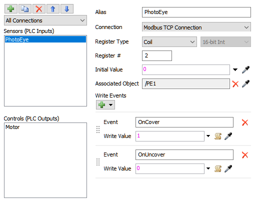
Each sensor can be associated with a series of events. You can specify which events you want that sensor to listen to. For example, if you are listening to a photo eye, you might set up the sensor to listen to the "On Cover" and "On Uncover" events. The specific events that are available for each sensor depends on what kind of object the sensor is connected to in the simulation model. See Key Concepts About Events for more information.
Controls (PLC Outputs)
Controls are the PLC's outputs. The controls tell the system how to respond and what to do. For example, controls could issue instructions to:
- Open a valve on a door or a lock
- Control a motor that drives a particular process
- Issue a warning
- Cause chutes to open and close
- Tell a motor running a conveyor belt to start, stop, or move to a particular position
Based on the inputs (values) it receives, the PLC will issue controls that will tell the system what actions to take.
Ladder Logic
Ladder logic is a programming language that is used to develop the software for PLCs used in industrial control applications. While you will not use actual ladder logic in FlexSim, you can use process flow activities to communicate how a PLC's ladder logic should be programmed.
Active vs. Inactive Connections
When you first set up your emulation project, you'll need to create a server connection. You'll connect all the variables (the sensors and controls) to this connection. By default, this server connection will be inactive, which means that the server connection will only be internal to FlexSim. When the simulation model runs, the server will get inputs from the simulation model. You should leave the server connection inactive if you are building a theoretical or future-state model that has not yet been implemented.
When you move into the phase of the emulation project where you need to test the PLC logic, you can then make the server connection active. You'll need to connect your computer to the actual server and then set up the credentials in FlexSim to access the server. You'll also need to assign all the emulation variables to their appropriate variables on the server.
When you run your simulation model while the server is active, you should ideally only run the model at a speed of 1.00, which means that the model will run in real time. You'll want to keep the simulation model and the actual system running at the same speed so that you can test the PLC logic and compare the actual system with the simulation model. See Validating PLC Logic for more information.
Best Practices
The following sections outlines a few best practices that you should consider when designing PLC logic in FlexSim:
Collaborate with the PLC Programmer
Since the end-goal of an emulation project is to hand off the simulation model to a PLC programmer, you should consider working with the PLC programmer to ensure that the way you build the logic in process flow matches the programmer's expectations. For example, you might want to get advice on how to organize the process flow logic in a way that is easy for the programmer to follow and understand.
Document Your Logic
Since the goal of emulation is to facilitate communication between the simulation expert and the PLC programmer, it's crucial that you add documentation to your process flow. At the very least, make sure you use clear activity and variable names that indicate the purpose of those elements in the process flow. Consider adding explanatory text to your process flow as well.