Creating and Importing Custom 3D Objects
Introduction to Custom 3D Objects
Although you can create an excellent simulation model using the default 3D objects available in the FlexSim library, you might want to customize your simulation model with 3D objects that look like the unique business system you are modeling. The topics in this section of the manual will guide you through this process.
Using Third Party Objects and Software
FlexSim recommends using AC3D to create static 3D objects. This software is relatively inexpensive, has a user-friendly interface, and is capable of making some high quality 3D objects. You can also import the raw .ac files created from AC3D directly in FlexSim. AC3D is available from www.inivis.com.
FlexSim can also import custom objects with bone animations made by third-party applications such as Blender, Poser, Mixamo, or 3ds Max. See Creating Custom Animations for more information.
You don't necessarily need to create all the custom 3D objects you need by yourself. One great resource you should consider researching is 3D Warehouse. 3D Warehouse is an open-source library where anyone can upload and download custom 3D objects made with SketchUp. The chances are good that someone has created an object similar to what you need. Consider searching the database as a way to save time.
Valid 3D Object File Types
The following object file types can be imported into FlexSim (listed alphabetically):
- .3ds
- .ac
- .ase
- .blend
- .cob
- .csm
- .dae
- .dxf
- .fbx
- .hmp
- .igs
- .irr
- .irrmesh
- .jt
- .lvo
- .lvs
- .lxo
- .md5mesh
- .mdl
- .ms3d
- .obj
- .off
- .ply
- .q3o
- .q3s
- .raw
- .scn
- .skp
- .stl *
- .stp
- .ter
- .wrl *
- .x
- .xgl
- .zgl
Guidelines for Creating Custom 3D Objects
Before creating a custom 3D object, there are a few general guidelines you should keep in mind, as discussed in this section.
Reduce the Number of Polygons
In order to ensure that your simulation model runs as efficiently as possible, you'll want to reduce the number of polygons in your custom 3D objects. 3D files typically include more information than is necessary. Removing excess polygons will improve the visual performance of your model.
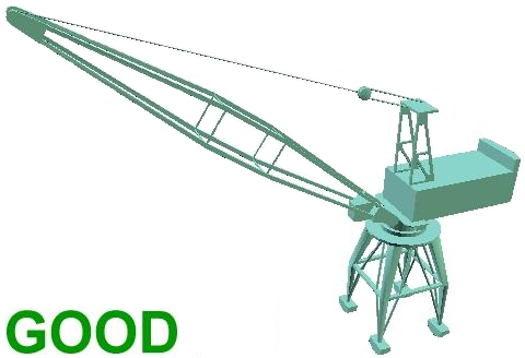
The following image is an example of a 3D object with unnecessary polygons:

Notice the hoist line and rope combines several polygons in order to make it look more like steel wire. The crane's chassis also has fencing on top which uses additional polygons. While this crane does look realistic, these details and extra polygons aren't necessary and will not look optimal in FlexSim.
The following image is an improved version of this 3D object:
This 3D object removes those unnecessary polygons while still retaining a realistic look.
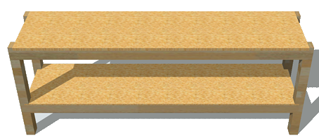
Textures vs. Polygons
As an alternative to using polygons to create realistic effects, consider using textures instead. Textures are flat images (like a .png file) that can be added to the surface of a 3D object to give it the appearance of sophisticated textures and details. For example, this 3D workbench has simple polygons and uses a wood grain texture on its surfaces to give it a realistic appearance:
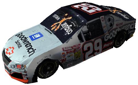
This 3D car uses textures to look like a race car's wraps and to add details to the tires:
The following are a few tips when using textures:
- Share textures among objects. Whenever possible, try to consolidate objects in your 3D creation software and share the same texture among multiple objects. Consolidating textures reduces the number of OpenGL state changes required, which can significantly improve performance.
- Use transparent images. Image files that support transparency (like .png files) work better in FlexSim. FlexSim will read the transparency of the image and display it properly.
Importing 3D Objects
You can change the shape of any of the fixed resources or task executers in the 3D model. (See Importing Custom 3D Flow Items for more information about changing the shape of flow items.) For example, if you want to have the functionality of a processor but you would prefer that it looks more like a workbench, you can change the processor's shape.
To change an object's shape:
- Double-click the object to open its Properties window.
- In the General tab under the Appearance group, click the arrow next to the Shape box to open a menu. Select Browse.
- Navigate to the location of the 3D file on your computer. Then select Open. The custom 3D shape will appear in place of the old object.
Troubleshooting
Occasionally when you import your own custom files, you might experience problems with scaling, flow item offsets, or visuals. The following sections will discuss possible solutions to these problems.
Adjust the Scale
3D files are not necessarily drawn in feet or meters and may need to be rescaled to work appropriately in FlexSim. There are three ways to adjust the scale of a 3D file:
- Appropriately scale the file in the 3D program.
- Scale the visual tool or other object in FlexSim that the file is imported into.
- Use an xrl file for wrl files.
If you are using 3DS or .ac, then you can just make sure the object is scaled properly in whatever 3D software you use. Then import it into FlexSim, and it will automatically import to the correct size. Just make sure that your units in your software are the same as the units you are going to use in FlexSim.
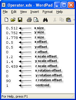
Xrl files are used to make imported wrl shapes conform to the object they are imported
into. xrl files must have the same names as the objects they modify. For example:
crane.wrl and crane.xrl. The xrl file is a text file made up of 13
values separated by carriage returns. You can edit this file using notepad or wordpad, as
shown in the following image:
Getting the Object's Color or Texture to Bleed Through
For .3ds and .ac files, you can have the FlexSim object's color bleed through on certain shapes in the file. You can do this in one of two ways:
- Give the shape an ambient color value of rgb: (0.235,0.235,0.243) in your 3D software
- Append "_fsclr" to the end of the shape's material name in your 3D software
For .3ds and .ac files, you can also have the FlexSim object's defined texture show up on
the shape instead of the texture defined in the file. To do this, just add a texture named
fstx.png to the object in your 3D software.
Adjusting Shape Factors
Each media file that is imported has certain scaling and offset settings which may cause the 3D shape that you import to not fit within the object's boundaries. If this is case, you can edit the object's 3D shape factors to fit the 3D shape within the object's yellow bounding box.
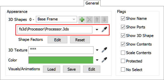
The following image shows modified shape factors for a processor's 3D shape:
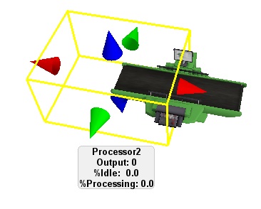
The image above shows modified shape factors for a Processor's 3D shape. Notice that the yellow bounding box reflects the true position and size of the processor, but the 3D shape has been offset in the x direction.
To change the shape factors:
- Double-click the object to open its properties.
- In the General tab, use the properties under the Position, Rotation, and Size group to adjust the shape factors.
Changing the Position of Flow Items
If the height of the surface of the custom 3D object is different than the height of the original object, you might need to adjust the position of the flow item when it enters the object. To adjust the flow item's position:
- Double-click the object to open its properties.
- In the Triggers tab, click the Add button to open a menu. Select On Entry to add this trigger.
- Click the Add button
 next to the On
Entry trigger to open a menu.
next to the On
Entry trigger to open a menu. - Point to Visual, then select Set Location to open a picklist.
- Confirm that the Object box says item. (If not, click the arrow and select item from the menu.)
- Make sure the X, Y, and Z properties match the dimensions of your custom object. You might have to experiment with different numbers until it's right.
- Click the Apply or OK button to save the chages.
- Run the simulation model to test if the flow items are positioned correctly.