Task 3.1 - Import and export
Task Overview
In this task you will learn about the Berth and Loading Arm object in FloWorks. The Berth is not a flow object, but a Fixed Resource that can also be used outside of a fluid or bulk context to model vessels loading or unloading. The Loading Arm forms the link between the Berth and the fluid objects: instead of giving the berth a fixed processing time, it allows the (un)loading process to be determined by the capacity and flow rates of the vessel and the onshore flow origin (such as a tank, stock pile, mixer or even a flow source) or destination.
Step 1 Creating the infrastructure
In this step you will first set up a basic infrastructure for the model. Create a new model, with as units seconds, meters and liters.
To give the model a more realistic feel,
consider downloading a map to an image file on your computer and setting it as the model background.
To do this, drag a Background object into the model from the Visual section of the Drag-Drop Library, select
“Image file” and browse to find the image on your computer. For example, enter the path
modules\FloWorks\manual\Tutorials\LoadingPointsAndBerths\3-1ImportExport\Images\background.png
to use an image file included in this tutorial.
Alternatively, you may use the GIS module included with FlexSim.
Add a (regular, flow item) Source at a production location near the shore. Also add a queue and a FloWorks Berth to the model: click the Loading Point object in the library and drag or select and add a Berth from the popup menu. 'A'-connect the objects in the order Source -> Queue -> Berth.
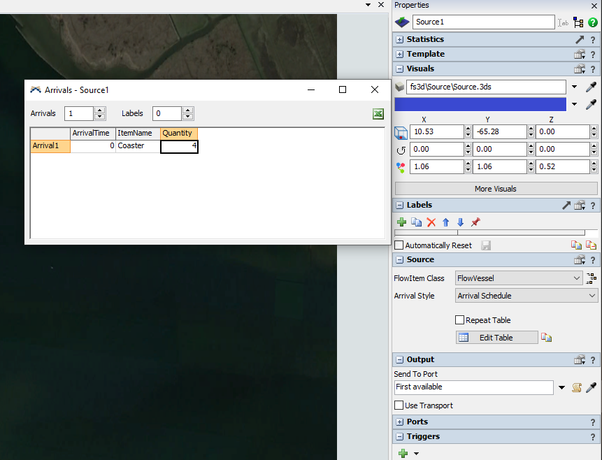
Set the Arrival Style of the source to “Arrival Schedule” and the FlowItem Class to “Flow Vessel”. In the arrivals table, give the flow items a name of “Coaster” and set the Quantity to 4.
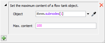
We want to have some control over the size of our vessel's loads. Add an "On Creation" trigger to the source,
navigate to the "Compartment (FloWorks)" item and select "Set compartment size". You can leave the Object, set the
maximum content value to 100.
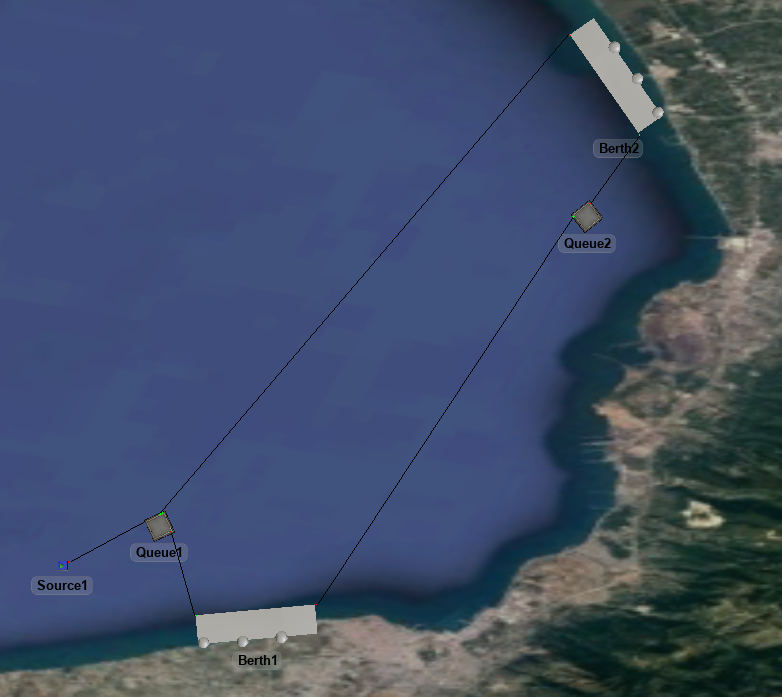
Create a queue and a berth at a demand location of your preference. Connect the production side berth to the demand side queue, the demand side queue to the demand side berth, and the demand side berth to the production side queue, to get a loop as shown below.
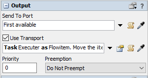
Select both queues and both berths by holding control and clicking these four objects. In the Quick Properties window, check the “Use transport” box and from the dropdown below it, select the option “Task executer as flow item”. This will make the vessels move across the model as if they are sailing between the objects, rather than getting moved instantaneously.
To test the model, set the “(Un)loading time” of both berths to 10. When you reset and run the model, you will see the four coasters sail the loop between the berths, staying at each side for a fixed duration of 10 seconds. When you click on a vessel tank, you should see that it has a capacity of 100, as set by the source's On Creation trigger.
Step 2 Add production and consumption units
In this step, you will add the FloWorks objects that represent the production and consumption of the bulk material.
At the production side, add a Flow Source with a production rate of 3. Connect it to a newly created Flow Pile (click Flow Tank in the library and select the Pile visualization) with a maximum inflow rate and outflow rate of “unconstrained” (default for the inflow, you'll have to set it for the outflow) and a maximum content of 5000.
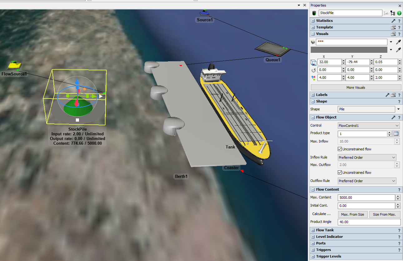
Create a similar stockpile at the other side (hint: copy and paste the one you have just configured) and connect it to a flow sink with a maximum inflow rate of 2. In addition, give this stockpile an initial content of 4000 so that it can bridge the time gap until the first coaster arrives.
Step 3 Connect the flow objects to the ships
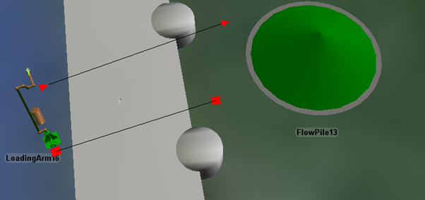
In this step you will add two Loading Arms to connect the stock piles to the tanks of the ships. Drag a loading arm into the model at the production side, near the berth.
Connect the stock pile to the loading arm with a regular (‘A’) connection. Then connect the loading arm to the berth using a center (‘S’) connection.
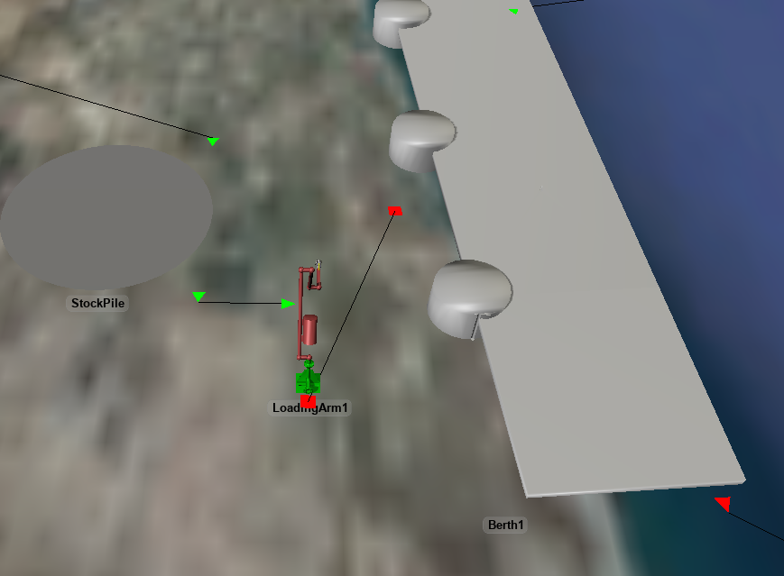
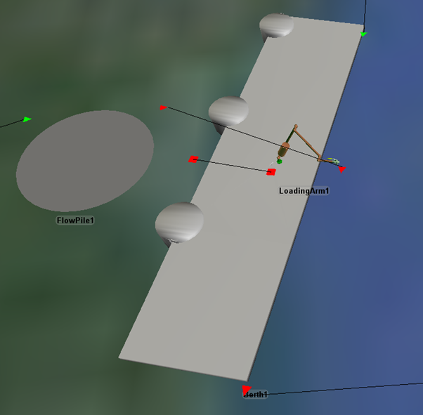
Once you have made these connections, you can reposition the loading arm so that it appears to be part of the berth.
Note that we have used the "Unconstrained rate" option in some places, but there has to be at least one constraint in the sequence stockpile → loading arm → vessel tank. Preferably you will put such constraints on the loading arm, as it makes it easier later on to dynamically change the loading rate. If you look at the Flow tab of the Loading Arm's properties you'll see that it behaves like a flow pump or valve, as far as controlling the flow is concerned, and it has a default max. flow rate of 10.
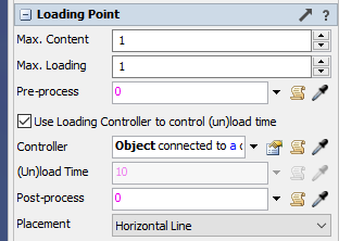
Recall that the berth still has a fixed processing time of 10 seconds. Instead, you will tell it to use the loading arm as a loading controller. This means that once a vessel enters the berth, the loading process will be deferred to the loading arm. That will take care of connecting to the vessel, and keeping track of the loading progress. Once the vessel's tank is full (or empty, in the case of unloading, or reaches some other content level that you specify) the loading arm will disconnect from the vessel's tank and control will be passed back to the berth to start post-processing and go through the Fixed Resource's regular send-to-port and exit process.
In order to do this, go into the berth's properties panel and tick the box “Use Loading Controller”. This will gray out the “(Un)loading time” field and enable to “Loading controller” field. The value of the latter is set to use the object connected to center port #1 by default, which is correct.
Now look at the consumption side of your model. Add another loading arm and create a center port connection
between the berth and the loading arm (remember, center port connections do not have a direction) but for
the ‘A’-connection make sure that it goes
By default, loading arms will assume that they are used to load a vessel, so you need to put it in unload mode. In the loading arm properties check the “Unload transporter” box to tell the loading arm that it needs to connect the vessel’s tank to itself rather than the other way around. For this loading arm, also set the maximum flow to 10.
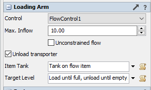
Last but not least: don't forget to tell the berth to use the loading arm by checking the “Use Loading Controller” checkbox!
Step 4 Measuring deferred production and consumption
When you run the model above for a while, you will see that it is not entirely stable. Eventually the production stockpile will fill up and the consumption stockpile will become empty. In this step, we’ll show you two different ways to quantify this effect.
At the production site, the flow source will eventually get blocked when the stock pile is full. Create a sink with an unconstrained inflow rate and connect the production source to it. When you change this model in the future, make sure that the flow sink is always at the second (in general: last) output port of the flow source. This sink will now catch any production that the flow source cannot release into the system.
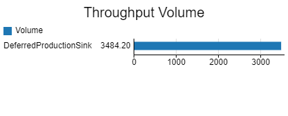
Click on the deferred production sink, and find the Throughput (Input/Output) field in the statistics panel of the Quick Properties.
There is a “Pin” ( ) button to the right of it, which allows
you to pin “Current Input and Output”.
) button to the right of it, which allows
you to pin “Current Input and Output”.
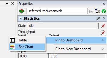
This will add a table to a new dashboard, showing you the amount of bulk that could not be stored to the stockpile.
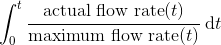
Another way of checking whether you are using the full capacity of the system, is by looking at the utilization. Utilization is defined for objects with a single flow rate, such as pumps, valves, sources and sinks (but not – for example, tanks). It is a percentage that basically indicates how much of the time the maximum flow rate has been used – in more technical terms, it is:
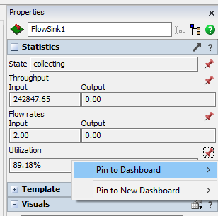
You can get an idea of how much shortage there is at the consumption side by considering the utilization of the sink. Find the utilization field in the statistics on the Quick Properties panel, and add the “Current Utilization” to the existing dashboard. As long as the flow sink can consume from the stock pile at the maximum flow rate of 2, the utilization will remain at 1 (100%). However you will see, when you run the model for an extended amount of time, that the utilization starts decreasing as soon as the stock pile runs dry. Eventually you will see it stabilize around a certain value, indicating which percentage of the time you can support the requested consumption rate in the long run.
This tutorial does not include an attempt to balance out the system, but using these metrics feel free to play with the production and consumption rates (or perhaps the number of vessels) to see if you can stabilize the flows.
Conclusion
In the next tutorial task, you will expand the vessels to have multiple compartments that can be loaded with different products. Continue to Tutorial Task 3.2 - Multi-compartment loading.