Key Concepts About Travel
Overview of Travel Systems
This topic will provide a high-level overview of different tools for controlling the travel paths for task executers such as operators, transporters, and the TaskExecuter object.
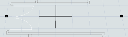
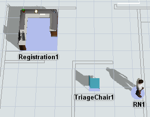
By default, when a task executer travels between two objects, FlexSim will simply choose the shortest distance between two points: a straight line. While this default travel logic might meet your simulation needs, in many cases it won't---especially if you're working with a specific floor plan. If task executers use the default travel system, they might end up traveling through other objects or through barriers such as walls. The following image shows an example of the default travel behavior:
Using one of FlexSim's travel tools instead of the default travel system will allow you to create more accurate travel paths. You can define the specific travel paths that task executers should use and/or you can create barriers that task executers will need to travel around (such as walls). In other words, you'll be able to create more accurate travel paths for your task executers. Travel accuracy has two main advantages:
- Accurate travel paths will give you better statistics - If task executers aren't traveling on the shortest distance between two points, that means their travel time might be longer. Even seemingly minor differences in travel time and distance can have a large impact on the overall statistics of your simulation model over time. Using accurate travel paths will ensure that those statistics are more representative of the actual business system you are trying to simulate.
- Accurate travel paths will look better visually - When task executers travel in a straight path between two objects, it sometimes makes them travel in ways that appear visually incorrect. For example, an operator might walk through an object or through the walls of a floor plan to get to its destination. Using a travel system to force task executers to walk around objects or barriers will help the model look more correct visually.
FlexSim has two different tools to create different travel systems for task executers:
- Travel Networks - Using this tool, you'll define the specific paths that task executers can use to get from one location to another in the simulation model.
- A* Navigation - Using this tool, you'll create travel barriers for task executers. Any fixed resources you connect to the A* system will also be treated as a barrier that cannot be passed through directly. The A* Navigator will then use these barriers and the travel threshold around fixed resources to calculate the shortest distance between two locations.
The following sections will discuss the two different travel tools in more depth as well as other important concepts related to travel systems.
How Travel Networks Work
As was stated above, when you use the travel network tool, you'll define the specific paths that task executers can use to get from one location to another in the simulation model. The following image shows the same model that was used in the previous image, but now the task executers travel on specific paths:
To use this tool, you'll follow a few basic steps:
- Add network nodes to the model - You'll start by dragging out network nodes (from the Library) and placing them at key points in the simulation model. In general, you'll want to put network nodes next to fixed resources to which task executers will need to travel. Then, you'll want to put network nodes at the beginning and end of a path you want them to travel (such as a hallway). The following image shows an example of two unconnected network nodes at the beginning and end of a hallway:
- Connect network nodes to create travel paths - You can connect two nodes using the same method that you would use to create input/output port connections (A-connects) between fixed resources. Once the nodes are connected, you'll see a line connecting the two nodes. The line will also have directional arrows indicating which directions of travel are allowed on that path:
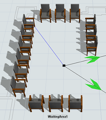
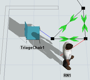
- Connect fixed resources to network nodes - If a task executer needs to travel to a fixed resource, you'll need to make sure it's connected to the travel network. Use an A-connect to connect a nearby network node to the fixed resource. A blue line will appear to show that the fixed resource is now connected to that node:
- Connect task executers to network nodes - Use an A-connect to connect a nearby network node to the task executer. This network node will act as the task executer's entry point to the travel network, so you should connect the task executer to a node that is near its starting reset position in the simulation model. A red line will appear to show that the task executer is now connected to that node:
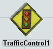
- Add a traffic controller to prevent collisions - Many simulation models will not need a traffic controller, but if you have a busy travel intersection where many different task executers might possibly collide, you might want to add a traffic controller object to manage the traffic. You'll connect network nodes to the traffic controller to define which paths should have restricted access. The traffic controller can then limit the number of travelers that are allowed to enter a particular path or area at a time.
- Change additional travel network properties - If needed, you can adjust properties on the entire network or the connection between two network nodes. You can determine whether connections will allow two-way or one-way traffic. You can also determine whether task executers traveling at a faster speed can pass slower task executers and, if not, how much space will be allowed between them on the path.
- Make the travel network invisible - Lastly, you can hide the travel network so that you don't have to clutter up the simulation model with travel network paths. Right-click and change the Network View Mode. If you select None, all of the network nodes and paths will disappear except for one node (the one you right-clicked). You can use the one remaining node to turn the visibility back on if needed.
When you reset and run the simulation model, FlexSim will calculate the shortest path for a task executer to take on the travel network any time a task executer needs to travel from one point on the network to another.
How A* Navigation Works
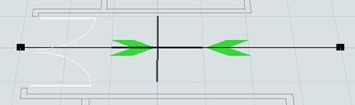
As was stated above, you'll use the A* navigation system to create travel barriers for task executers. Any fixed resources you connect to the A* system will also be treated as a barrier that cannot be passed through directly. The A* Navigator will then use these barriers and the travel threshold around fixed resources to calculate the shortest distance between two locations. The following image shows the same model that was used in the previous sections, but now the task executers travel by calculating the shortest path around barriers:
To use this tool, you'll follow a few basic steps:
- Add an A* Navigator to the model - From the Library, drag an A* Navigator into the model. You can place the navigator anywhere in the model, but most users prefer to put it in a spot that is slightly removed from the rest of the simulation model.
- Connect all the fixed resources and task executers to the A* Navigator - You can connect two nodes using the same method that you would use to create input/output port connections (A-connects) between fixed resources. You can also connect 3D objects in the A* Navigator's properties by sampling them as members. When a 3D object has been successfully connected to the navigator, it will have a purple background underneath it.
- Add any dividers or barriers to the model as needed - Dividers and barriers act as places that task executers have to walk around. In the Library, click the Divider or Barrier buttons to enter Create Divider or Create Barrier mode. Then you can click inside the model to draw the dividers or barriers. (It sometimes helps to turn off the model's main grid and turn on the A* grid visuals instead.)
- Check that the travel thresholds for fixed resources don't extend beyond the dividers or barriers - An object's travel threshold is comprised of red points surrounded by blue points. (See A* Travel Thresholds for a deeper explanation of how A* uses travel thresholds.) You'll want to move an object so that the red points in its travel threshold don't fall on the wrong side of A* dividers or barriers. Otherwise, it could make a task executer travel along an incorrect path to get to that entry point. The following image shows an example of a travel threshold extending beyond a divider:
- Make the A* visual guides invisible - After you've successfully tested your A* system, you can hide the visuals if needed. You can do this in the A* Navigator's properties.
When the simulation model runs and a task executer needs to travel from one point in the grid, A* will run a search algorithm to find the shortest path between points. The algorithm basically divides the model into a grid of nodes through which task executers might travel. Each node specifies the direction travel members can possibly move. The algorithm will look at nodes in the direction of travel and determine which direction is the fastest, including traveling diagonally between nodes. The grid of nodes can be modified by creating barriers restricting where the travel members can move.
The following image shows an example of a grid that has several barriers in place:
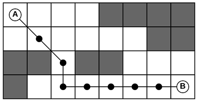
When a traveler needs to go from point A to point B, the A* algorithm would calculate the shortest path. Notice in this scenario that there is more than one possible path, but only the path that is marked is clearly shorter than the others. A* can adapt to changing conditions and find the ideal path.
A* Travel Thresholds
The A* Navigation system uses travel thresholds to calculate the shortest possible point between two objects. A fixed resource's travel threshold represents the possible entry points to which a task executer may travel when it is walking to that object.
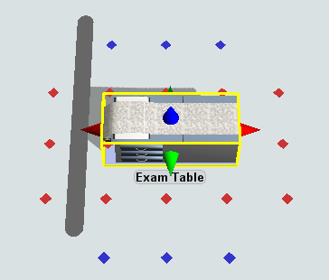
An object's travel threshold consists of two zones: a calculated path zone and a travel arrival zone. The following image displays these two zones on an object:
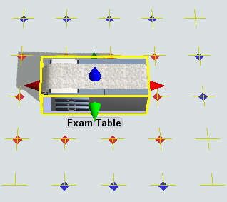
Notice that this image shows an object surrounded by red and blue points. These points indicate the two zones that make up the object's travel threshold. Each zone is described in the following table:
| Zone | Description | |
|---|---|---|
 |
calculated path zone | When a task executer needs to travel to this fixed resource, the A* Navigator will compute the shortest path between the traveler and any of the points in the calculated path zone. The traveler will then begin traveling following this shortest path. |
 |
travel arrival zone | The travel arrival zone won't be used by the A* algorithm to calculate a path, but the points in the travel arrival zone will be used to determine when the travel has arrived at the fixed resource. As soon as the traveler reaches any of the blue dots, FlexSim will consider the traveler as having arrived and the travel task as complete. In other words, the A* algorithm will first build the shortest path to a red dot. Then, if the resulting path includes blue dots, the algorithm will shorten the path to stop at the first blue dot on the path. The difference between the red and blue dots becomes more apparent when a fixed resource is especially long, for example when the object's x axis size is significantly larger than the object's y axis size. |
Travel thresholds can sometimes be the source of problems while using A*, causing strange travel behavior or animations. See Troubleshooting Travel Thresholds for instructions on how to fix common travel threshold problems.
Deciding on a Travel Tool
When deciding whether to use travel networks or A* navigation, you'll need to consider which system makes sense for your simulation project. For the most part, it's largely going to be a matter of personal preference. However, each system has different advantages and disadvantages, as explained in the following table:
| Travel Networks | A* Navigation | |
|---|---|---|
| Advantages |
|
|
| Disadvantages |
|
|
Try experimenting with both methods at first and discover which system makes the most sense for your simulation model project.