Working With Conveyor Objects
Introduction to Working With Conveyor Objects
For the most part, conveyor objects are similar to fixed resources and can be added, moved, resized, etc. using the same methods you would use for other 3D objects. (See the chapter on Using 3D Objects for more information.)
However, there are some key differences when working with conveyor objects:
- Starts and Ends - Conveyors have two ends, respectively called the start and the end in FlexSim. Although these two ends are connected, they can be moved, rotated, and resized independently. The start is where flow items enter the conveyor and the end is where flow items leave the conveyor.
- Moving Conveyors - You can move or resize a conveyor as a single unit, but you can also move or resize the start and end of a conveyor as separate units.
- Rotation - Conveyors cannot be rotated on their X, Y, or Z axes, but you can change the height (Z axis) of either the start or end of the conveyors.
- Curved Conveyor Radius and Angles - In addition to the usual X, Y, and Z axes, the curved conveyor has controls that allow you to edit its radius, start angle, and sweep angle.
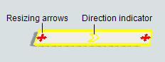
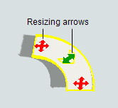
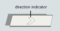
- Editing Controls - The editing controls also look and function differently on a conveyor. When a conveyor is highlighted, it will have a set of resizing arrows on both its start and end, as shown in the images below. The curved conveyor also has an additional green resizing arrow for adjusting its radius, start angle, and sweep angle. Each conveyor also has a direction indicator, which is a large unfilled arrow that shows you the direction the conveyor belt will move while operating.
The rest of the sections in this topic will provide more detail about these differences.
Adding Conveyors to a Simulation Model
Many of the conveyor objects can be added to the model the same way you would add any other object from the FlexSim Library: you simply click on the object in the Library and drag it into your simulation. (See Adding 3D Objects to a Model for more information.)
However, the straight conveyor, the curved conveyor, and the join conveyors each behave a little differently when added to a model. For instance, most of the other objects in the FlexSim Library have a default length, height, and width when you first add them to a simulation model. The straight and curved conveyor objects will have a default size if you click and drag them into the model. However, you also have the option to define the length and/or radius of the conveyors when you first insert them in your model, which will be discussed in the following sections.
Adding Conveyor Objects with Default Dimensions
If you want to add a straight or curved conveyor that has the default size, height, and width, simply click on the object in the Library and drag the conveyor into the model. This is essentially the same method for adding an object that you would normally use to add any other FlexSim object from the Library.
Adding Conveyor Objects with Custom Dimensions
The process for adding a conveyor object that has a custom length and/or radius is slightly different, but still relatively straightforward. To add a custom straight or curved conveyor to a simulation model:
- In the Library under the Conveyors group, click either the Straight Conveyor or the Curved Conveyor object to enter into conveyor building mode. When you are in conveyor building mode, your mouse pointer will change to a plus sign with either a Straight Conveyor icon or a Curved Conveyor icon next to it, as shown in the following image:
- Once in building mode, find the position in your simulation model where you want to place the start of the conveyor. When you click on that position in the model and start moving the mouse pointer in a different direction, you'll notice that it begins creating a conveyor object.
- Reposition the mouse pointer until the conveyor end is at the approximate length, angle, and radius you want it to be relative to the start. Click the mouse again to finish building the conveyor.

Connecting Conveyors
When you create a connection between a conveyor and another object, you make it possible for these objects to interact together. The most common way that objects interact in FlexSim is to transfer items from one object to another or send messages to another object.
The process for connecting conveyors is relatively similar to the process you would use to connect any other object from the FlexSim Library. However, there are a few differences to be aware of. The following sections will discuss some of the different methods for connecting conveyor objects.
Connecting Two Conveyors
Conveyors will automatically snap together if they are close enough. To snap two conveyors together:
- Click on one conveyor and drag it close to the edge of the other conveyor. When the edges of the two conveyors get close enough, they will snap together.
- After you release the mouse button, a transfer will appear that connects the two conveyors together. The transfer will look like a small square box that overlaps the edges of the two conveyors:
![]()
Using the Join Conveyors Object
Even though the Join Conveyors object is in the FlexSim library, it actually functions more like a tool than a 3D object. You can use the Join Conveyors tool to connect two conveyors with a curved conveyor:
- In the FlexSim Library under the Conveyors group, click on the
Join Conveyors object. You will then enter into
conveyor joining mode. When you are in conveyor joining mode, your mouse
pointer will change to a plus sign with a Join Conveyors icon
 next to it.
 - Once in joining mode, click on the center of the first conveyor you'd like to join. After clicking on the conveyor, you'll notice that a yellow line will follow your mouse as it moves, similar to the line that appears when you are connecting two FlexSim objects.
- Click on the second conveyor you'd like to join. You'll then notice a new curved conveyor will appear between the two conveyors. Two transfer points will also appear on both ends of the new conveyor.
Connecting Conveyors to Other FlexSim Objects
You can connect conveyors to other FlexSim objects such as fixed resources the same way you would normally connect objects in FlexSim. (See Overview of 3D Object Flows for more information.)
The primary way to connect conveyor objects to other objects is to create a port connection. However, unlike connecting normal FlexSim objects to each other, when you make a standard port connection (an 'A' connect) a conveyor to another FlexSim object, it will create a new entry transfer or an exit transfer, an in-between object that is associated with a specific point or range on the conveyor. An exit transfer is created when you connect a conveyor to another FlexSim object. An entry transfer is created when you connect a FlexSim object to a conveyor.
Connecting Motors and Merge Controllers
The motor and merge controller conveyor objects will usually only be connected to either a straight or curved conveyor. When connecting the motor and merge controller to a conveyor, you should use an input/output port connection (an 'A' connect). NOTE: This will not act like an input/output port but will merely serve as a reference point between the objects.
You might possibly want to make a port connection between the motor and merge controller objects and a non-conveyor object such as a task executer. In that case, you should create a center port connection (an S-connect). A center port connection will allow the motor or merge controller to send messages to other non-conveyor objects.
Moving and Resizing Conveyors
Like other 3D objects, conveyor objects can be moved or resized using either the Quick Properties pane or your mouse. (See Moving, Rotating, Resizing 3D Objects for more information.)
However, the key way in which conveyors are different is that they have resizing arrows at the start and end of the conveyor. Curved conveyors have an additional green resizing arrow that can be used to change the radius of curved conveyors:
The following sections will explain the differences for using either a mouse or Quick Properties to move or resize conveyors.
Using the Mouse to Move or Resize a Conveyor
In order to use your mouse to move or resize a conveyor, you must first click once on the conveyor to highlight it. After you've taken that step, use the steps listed in following table:
| Task | Process | Demonstration |
|---|---|---|
| To move the entire conveyor | Click anywhere on the conveyor (except on the resizing arrows) and drag the conveyor to the desired position. |  |
| To move either the start or end of the conveyor | Click the resizing arrow on either the start or end of the conveyor. Drag the start or end to the desired position. |  |
| To change the height (Z-axis) of the entire conveyor | Click anywhere on the conveyor (except on the resizing arrows), and holding down both the left and right mouse buttons, move the mouse up or down until the conveyor is at its desired height. |  |
| To change the height (Z-axis) of either the start or end of the conveyor | Click the resizing arrow on either the start or end of the conveyor, and holding down both the left and right mouse buttons, move the mouse up or down until the start or end is at its desired height. |  |
| To change the length of the conveyor | Click the resizing arrow on either the start or end of the conveyor. Drag the start or end to the desired length. |  |
Using Properties to Move or Resize a Conveyor
You might want the location, rotation, and size of the conveyor to be more precise in your model. In that case, it's generally a good practice to use your mouse to move or resize your conveyor until it is in the approximate position or size you want it to be. Then you can use the Properties pane to make it more precise.
When you highlight a conveyor by clicking on it, the right pane displays the Properties for that specific conveyor. The controls that appear in Properties will vary depending on whether you clicked a straight or curved conveyor. Both kinds of conveyors have boxes that adjust the position and size of the start and end of the conveyor, as illustrated in the following image. However, curved conveyors have additional boxes that adjust the radius, start angle, and sweep angle. The following image shows the Quick Properties for a curved conveyor:
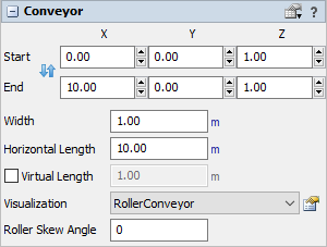
Start adjusts the X, Y, or Z position of the conveyor's start. End adjusts the conveyor's end.
A conveyor's length is based on the position of the start relative to the end. For example, if a conveyor is parallel with the X-axis on the grid with its start at the 0.0 position and the end is in the 10.0 position, the conveyor will be 10 units long. The same is true for the other axes. Experiment with some of the Properties to get your conveyor exactly the way it should be.
Changing the Radius and Angle of Curved Conveyors
Curved conveyors have three additional properties:
- Radius - The radius of the conveyor relative to the midpoint of the hypothetical circle around which the conveyor is drawn. Changing the radius will affect the length of the conveyor because it makes this hypothetical circle larger.
- Start Angle - The angle of the start end of the conveyor relative to the simulation model grid. For example, if the start angle is set to 90, the edge of the conveyor's start direction will be perpendicular to the x-axis of the model.
- Sweep Angle - The angle of the end of the conveyor relative to the start angle. For example, if the start angle is set to 45 and the sweep angle is set to 90, the edge of the conveyor's end direction will be 135 degrees offset from the x-axis of the model.
You can use either the mouse or the Properties pane to change the radius, start angle, and sweep angle of curved conveyors.
To change the radius, start angle, or sweep angle of a curved conveyor, you must first click once on the conveyor to highlight it. After you've taken that step, use the steps listed in following table:
| Task | Process | Demonstration |
|---|---|---|
| To change the radius | Click the green resizing arrow in the middle of the curved conveyor and drag the mouse to the desired radius. |  |
| To change the start angle | Click the red resizing arrow on the start end of the curved conveyor and drag the mouse until the edge of the start is at the desired angle. |  |
| To change the sweep angle | Click the red resizing arrow on the end of the curved conveyor and drag the mouse until the edge of the end is at the desired angle. |  |
Reversing the Direction of a Conveyor
Every conveyor has a large arrow on it that indicates which direction flow items will travel on the conveyor:
To change the direction that items travel on a conveyor:
- Click the conveyor to highlight it.
- In the Properties pane, under the Conveyor group, click the
 button. The direction indicator on the
conveyor will now point in the opposite direction.
button. The direction indicator on the
conveyor will now point in the opposite direction.
Copying Conveyors
Conveyors can be copied and pasted using many of the same methods you would use to copy and paste other 3D objects. See Copying and Pasting 3D Objects and Properties for more information.
However, if you know that you're going to build many similar conveyors with similar properties and logic, you should create a specific conveyor type for your conveyor. That way when you build any other conveyors, you can assign it to that particular conveyor type and it will immediately import the pre-defined settings you saved. See the next section for more information.