Connecting to an OPC UA Server
Overview
Emulation module makes FlexSim able to connect to OPC UA servers for data exchange.
Several steps are necessary to build a fully functional example:
- Install and configure an OPC UA server.
- Configure data exposed by the OPC UA server.
- Prepare a FlexSim model and connect it to the OPC UA server.
- Test the model with the OPC UA server connection.
Step 1 Install and configure a OPC UA Server.
In the market are available many OPC UA servers either commercial product or open project.
For this tutorial as OPC UA server we will use the KepwareServerEX 6, available from Kepware web site.
A full functional demo version is available and can be downloaded using the link above.
When installed you can access to the server functionality from the windows system tray:
Doing mouse right click you can access the server functionalities:
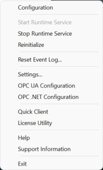
From this menu select the "OPC UA Configuration" item.
This will open the "OPC UA Configuration Manager" that allow to define the list of 'server endpoints', i.e how this server can be reached.
By default two endpoints using the TCP protocol are created by the installer:
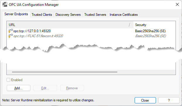
First endpoint specify a URL that allow to connect the server using the
loopback interface of the host, i.e. connect only from inside the host.
Second endpoint specify a URL using the current windows host-name, i.e.
allow to connect the server from outside, usually from another host in
the local network.
First is enabled, second disabled, by default.
To simplify the tutorial some adjustment to this configuration are
useful.
Clink on the first endpoint (127.0.0.1) and press "Edit..." to open the
"Endpoint Definition" page:
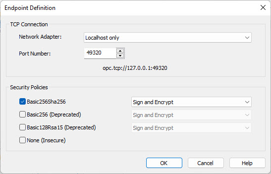
Check the "None (Insecure)" option and press "OK" to save the change, then close the "OPC UA Configuration Manager".
Now the OPC UA Server is installed, configured and ready to be used.
Step 2 Configure data exposed by the server
Second step is to configure the data exposed by the OPC UA server that will be subsequently accessed by FlexSim.
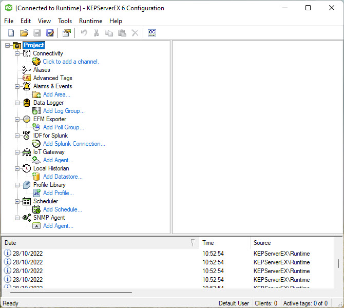
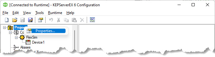
In KEPServerEX 6 this can be done with a mouse right click on the Kepware icon into the windows system tray and selecting "Configuration".
Alternatively search for the app "KEPServerEX 6 Configuration" or a desktop icon can be available.
Below the configuration page that will be shown:
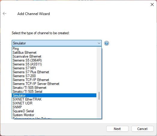
Then press "Next".
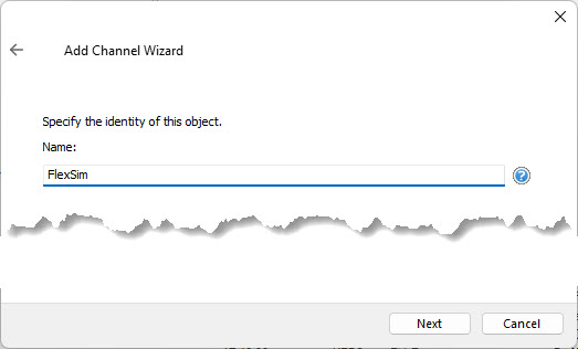
Enter the a name for the for the new channel and press "Next"
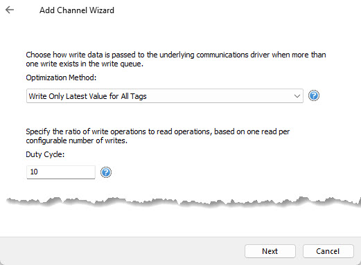
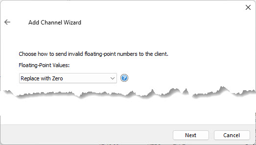
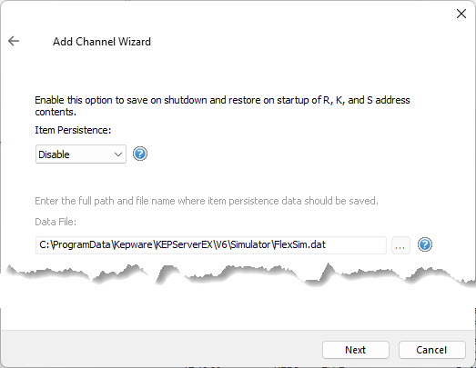
For next three pages leave the parameters at defaults values and press "Next":
When last page of the creation wizard appear:
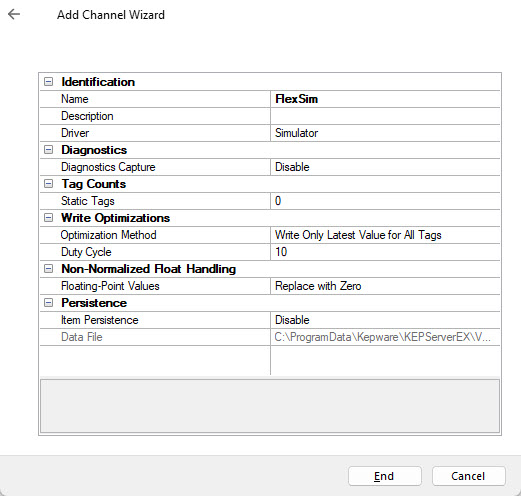
press "End" to create the communication channel an close the wizard.
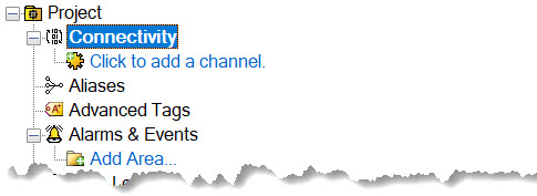
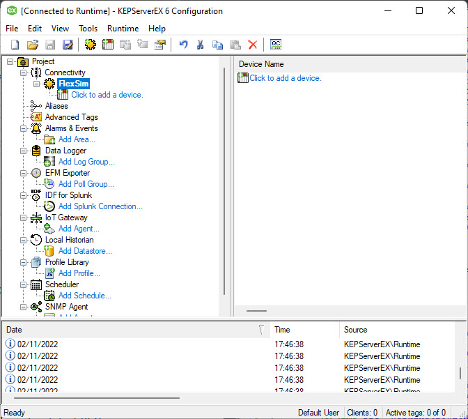
The channel is now created and you have to create a new "device" under
it.
To do this click the "Click to add a device" icon:
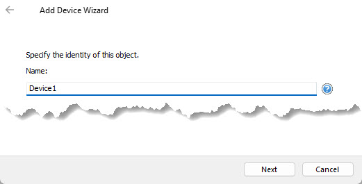
The "Device Wizard" will appear:enter a name for the device and press "Next"
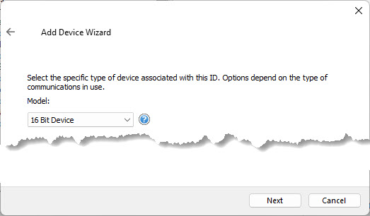
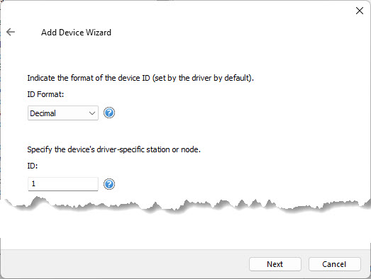
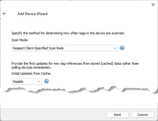
For next three pages leave the parameters at defaults values and press "Next":
When last page of the creation wizard appear:
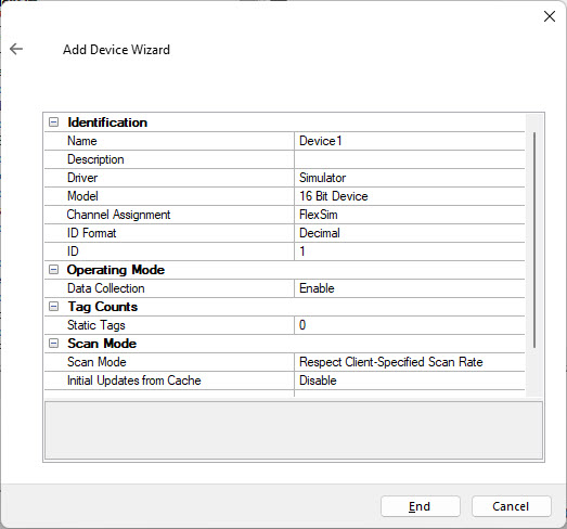
press "End" to create the device an close the wizard.
Select the "OPC UA" from the "Property Groups" and change "Allow anonymous login" to "Yes":
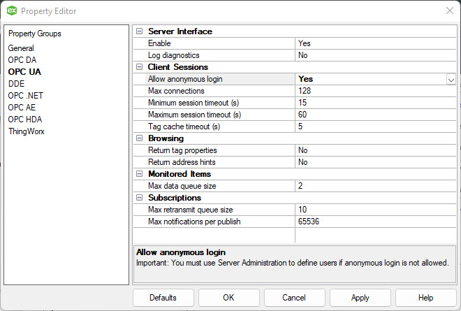
Then press "OK" to save the configuration.
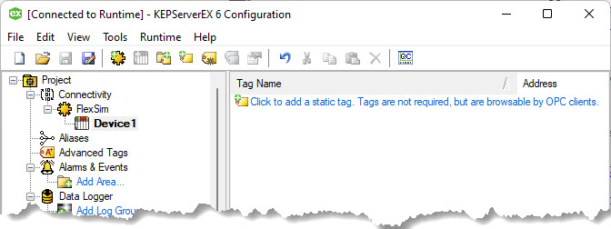
Move back to the "Device1" and select "Click to add static tag" into
the tag list on the right panel.
The properties edit to configure a newly created tag will be shown:
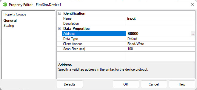
Set the properties as in the picture above:name equal to
'input' and address equal to 'B0000'.
Press 'OK' to confirm tag parameters.
Repeat the produce to create another that with name equal to
'output' and address equal to'B0001'.
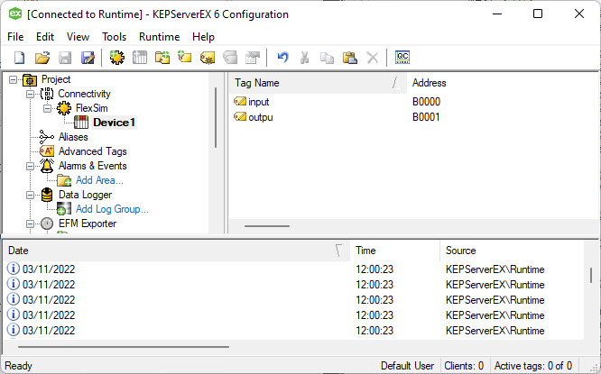
Now the OPC UA server expose two tags that can be read/written by OPC UA clients, like FlexSim is.
Step 3 Prepare a FlexSim model
Prepare a FlexSim model to connect to the device.The model that we will use for this tutorial represents a really simple production system where a box item is packaged into a tote:
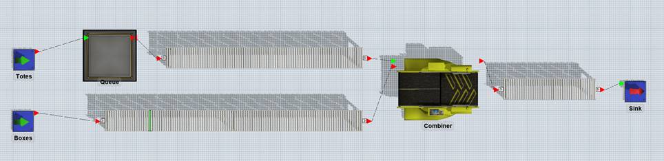
Build a model with two sources (one for boxes and one for totes), a queue for totes and a combiner that will join boxes and totes.>
Connect the elements with conveyors, as represented in the figure above and set conveyor speed to 0.5 m/s.>
Rename the sources to “Boxes” and “Totes”: Totes source is configured to produce 100 totes at time 0, Boxes source is configured to produce a box every 10s.>
A photo-eye is placed on boxes conveyor, approximately 1 meter before totes conveyor start.
Combiner puts a box into a tote in 5 seconds.
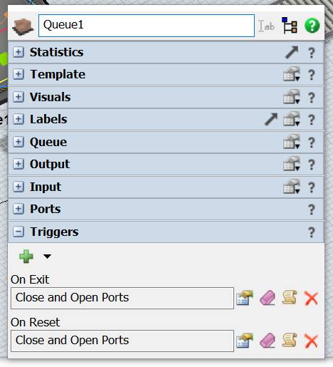
At last, configure the queue to close its outputs at reset and every time that a tote exits from it.
 >
>
Step 4 Test the model with OPC UA connection
At first, we will create an OPC UA connection to connect our model to the server.
The OPC UA server is a communication gateway then it is not a tool to
create control logic as PLC do.
This mean that "test the model with OPC UA" its only related to the
communication channel, the control logic for this tutorial, must be
provided, by hand, by the user.
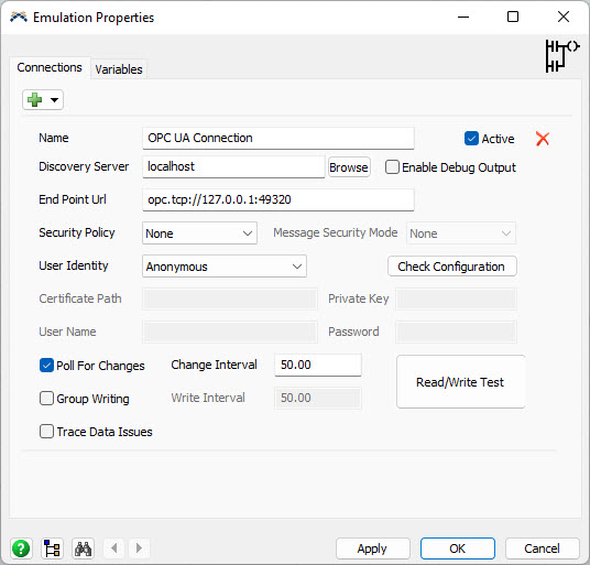
In the "End Point Url" enter the URL of the OPC UA Server's endpoint: for this tutorial is the string "opc.tcp://127.0.0.1:49320".
Leave "Security Policy" and "User Identity" set to "None" and "Anonymous".
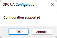
Press "Check Configuration" button: if everything is all right you should following message.
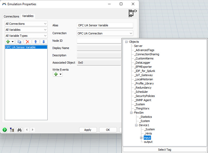
Click on the "Variables" tab and from the (+) sign select "OPC UA Sensor Variable".
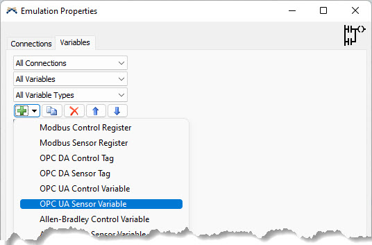
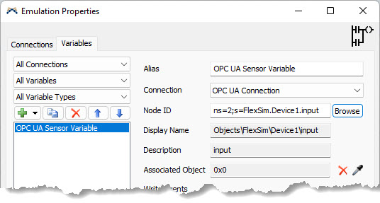
This will add a "OPC UA Sensor Variable" that will be bind to the "input" tag.
To to this simply press the "Browse" button and navigate up to reach the "input" node.
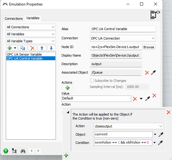
Repeat previous step creating an "OPC UA Control Variable" paired to the "output" tag:
At this point the connection between FlexSim variables and OPC UA tags is established. It’s necessary to define how FlexSim models drives PLC input and how PLC’s output is managed by FlexSim as well.
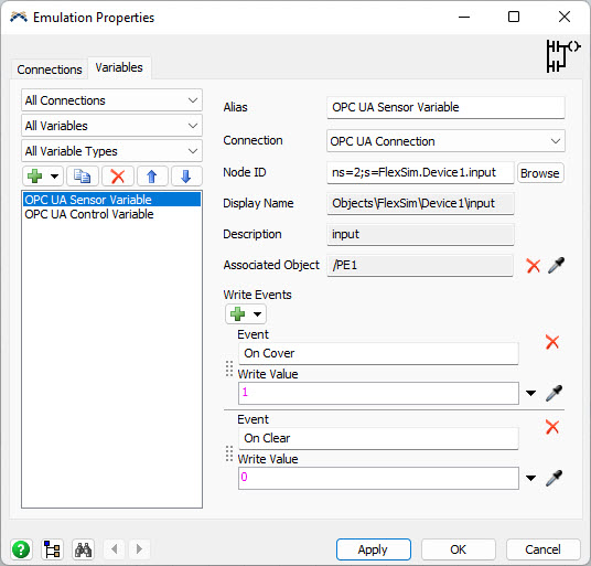
In our model we want that – when a box covers the photoeye – the "input" tag is set to 1 and when the "output" tag is set to 1 a tote is released from its queue.
The "input" tag should be reset to 0 when the photoeye is clear.
To do this, select the "OPC UA Sensor Variable", associate it to the photoeye and configure it to write values 1 and 0 when the photoeye is covered and cleared.
Also set the initial value to 0 to reset the "input" tag at model reset.
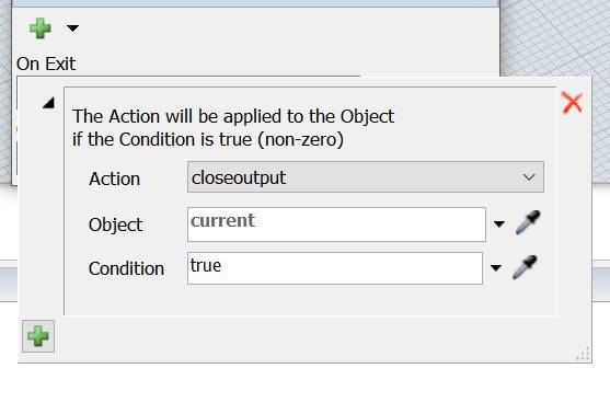
Now select the "OPC UA Control Variable" and associate it to the Tote queue.
Then configure a new action and set the queue open its output when the PLC value turns from 0 (oldValue) to 1 (newValue):
Now the model is fully configured and can be reset and run.
Remember to set the FlexSim’s run speed to 1.
Remember that the control logic must be supplied manually because OPC
UA is only a communication gateway.
So to test the model we need to manully set "output" tag to 1 when
"input" tag change to 1.
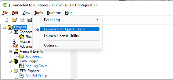
To allow this open the "KEPServerEX 6 Configuration" and from the menu "Tools" select "Launch OPC Quick Client":
The client will open and select the "FlexSim.Device1" node on the left to show the current values of the tags:
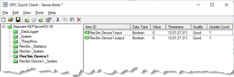
Each time the value of "input" tag change to 1 mean that a flowitem covered the /PE1 photoeye and you can change the "output" tag manually to 1.
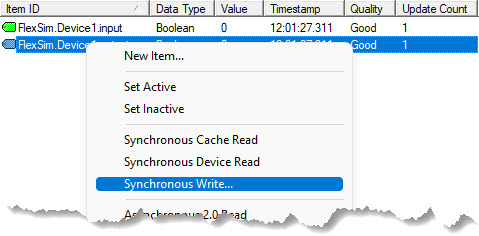
To update a tag value do a mouse right click and select "Syncronous Write"
Then write 1 in the "Write Value" column an press "Apply"
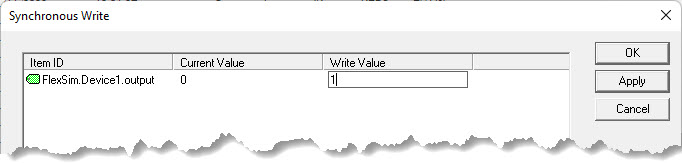
New value will be written and a flowitem will be relased from the Queue
in the FlexSim model.
This conclude this tutorial that shown how to create and connect a OPC
UA Server from Flexsim and how to use to control (manually) a running
model.