Connecting to PLCs or simulators of Beckhoff product family
Overview
Emulation module makes FlexSim able to connect to PLCs or PLC simulators of Beckhoff family.
Several steps are necessary to build a fully functional example:
- Create a Beckhoff project.
- Write the PLC code, compile it and download it to a real or simulated PLC.
- Prepare a FlexSim model and connect it to the PLC.
- Test the model.
Step 1 Create a TIA Portal project
In this tutorial TwinCAT will be used.
Open TwinCAT and select Create a new project command:
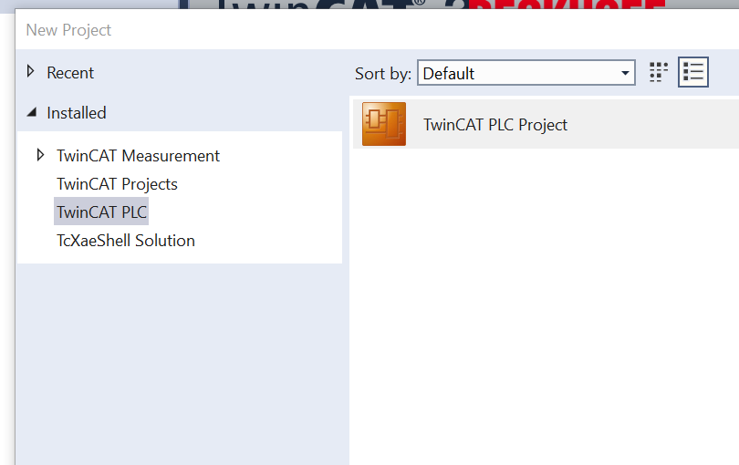
Create a new project and call it “tutorial”, then open the project view.
TwinCAT will ask for a new item: select "Standard PLC Project" and add it.
Step 2 Write the PLC code
Write the PLC code, compile it and download it to a real or simulated PLC.In this tutorial we will realize a simple delayer where a digital input is delayed in output of 1 seconds.
Once the project is created, right click on project name under the PLC section and open the item related:
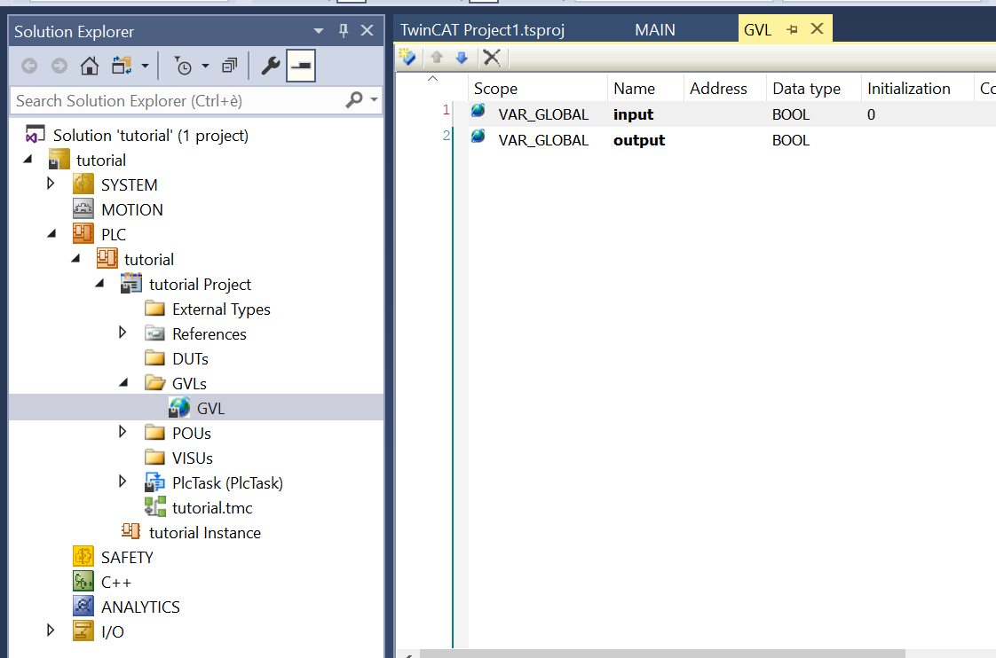
Go to "GLVs" item, click on the "GLV" item and add two BOOL global variables: name it "input" and "output".
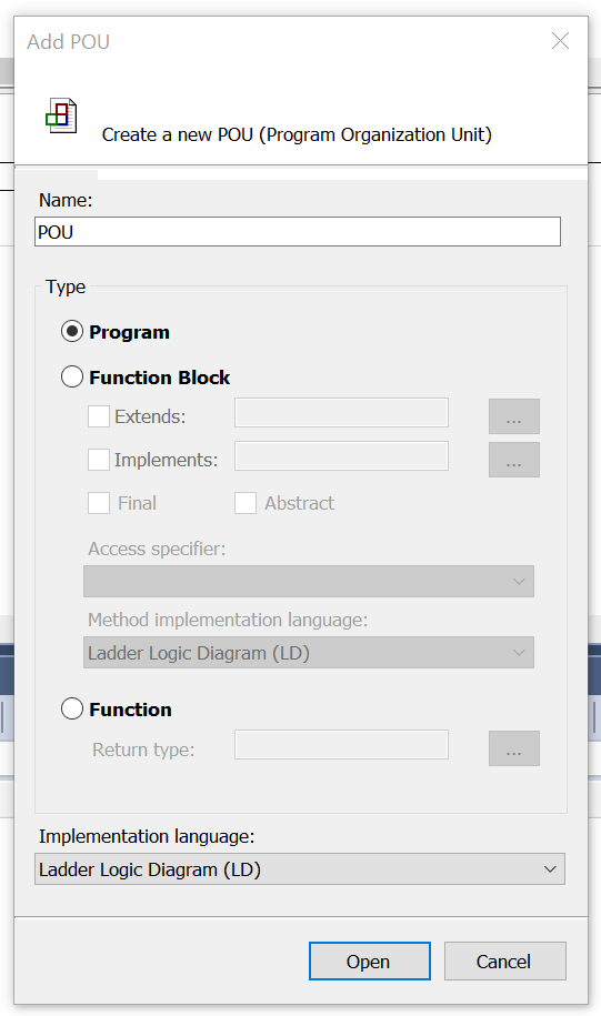
Then go on "POUs" section and remove the existing "MAIN" item (if any). Then create a new POU (right click on the POUs item to create it), selecting "Program" as Type and "Ladder Logic Diagram (LD)" as Implementation language.
After the block is created, implement in it the following ladder network:
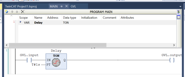
In this program block, when the "input" variable is set to 1, the "output" variable is set at 1 too with a delay of 1 second.
Remember to deleted unused input/output connections from the TON block: otherwise the program will be not compiled.
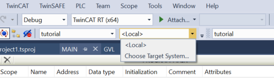
At this point go to the targets combo and click the "Choose Target System..." item
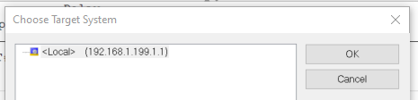
If you have a fresh installation, you should have a <Local> connection: copy the NetID (192.168.1.199.1.1 in this example).
Now the TwinCAT project is complete: you can activate it using the "Activate Configuration" button.
Step 3 Prepare a FlexSim model
Prepare a FlexSim model to connect to the device.The model that we will use for this tutorial represents a really simple production system where a box item is packaged into a tote:
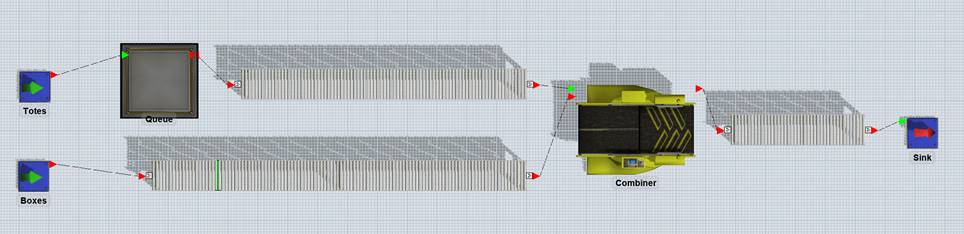
Build a model with two sources (one for boxes and one for totes), a queue for totes and a combiner that will join boxes and totes.>
Connect the elements with conveyors, as represented in the figure above and set conveyor speed to 0.5 m/s.
Rename the sources to “Boxes” and “Totes”: Totes source is configured to produce 100 totes at time 0, Boxes source is configured to produce a box every 10s.>
A photo-eye is placed on boxes conveyor, approximately 1 meter before totes conveyor start.
Combiner puts a box into a tote in 5 seconds.
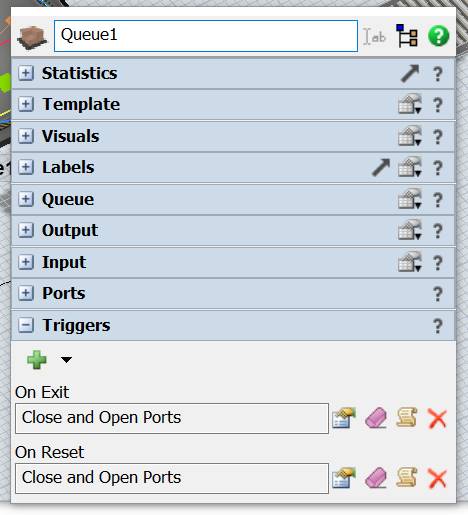
At last, configure the queue to close its outputs at reset and every time that a tote exits from it.
Step 4 Test the model
At first, we will create a Beckhoff connection to connect our model directly with the simulated instance hosted by TwinCAT and already running on it.
On FlexSim, create a new Beckhoff Connection by adding a new Emulation/Connection from the Tools menu.
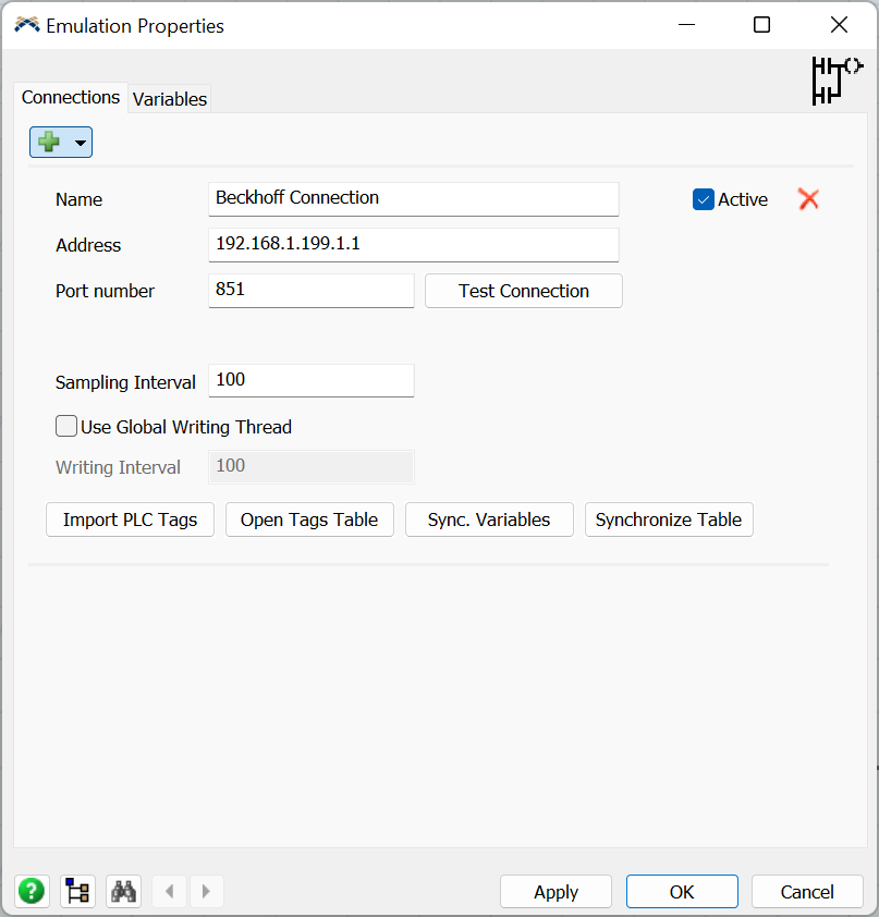
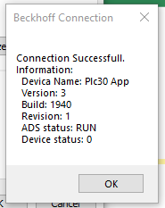
Insert the NetID you copied before into the Address field and press “Test Connection” button: if everything is all right you should see a detailed message.
If the connection is successful, it's possible to import the variables pressing the "Import PLC Tags" button.
The TAGS table will appear.
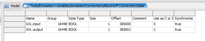
In order to transform the TwinCAT variables into FlexSim objects, mark the "GLV.input" TAG as "S" (sensor) and set the relative field in the Synchronize column as "true".
Do the same with the GLV.output variable, but mark it as "C" (control).
Then press the "Synchronize vars" button in the connection panel, to import the selected TAGs as FlexSim's sensor and control.
The Variables tab of the Emulation panel should contain the imported items.
Now, it’s necessary to define how FlexSim models drives PLC input and how PLC’s output is managed by FlexSim as well.
In our model we want that – when a box covers the photoeye – the PLC input is set to 1 and when the PLC output is set to 1 a tote is released from its queue.
The PLC input should be reset to 0 when the photoeye is clear.
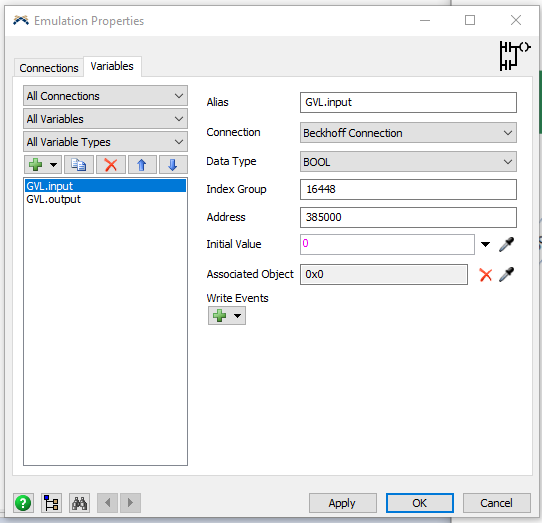
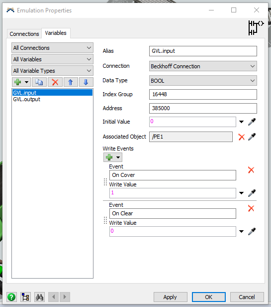
To do this, select the input variable, associate it to the photoeye and configure it to write values 1 and 0 when the photoeye is covered and cleared.
Also set the initial value to 0 to reset the PLC input at model reset.
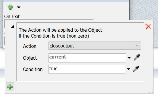
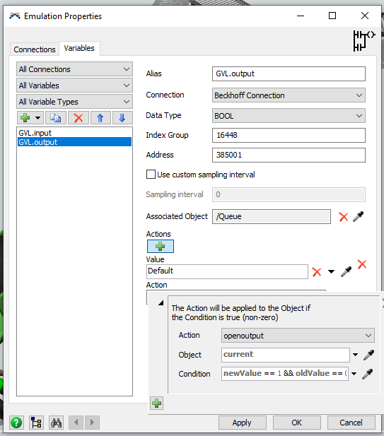
Now select the output variable and associate it to the Tote queue.
Then configure a new action and set the queue open its output when the PLC value turns from 0 (oldValue) to 1 (newValue):
Now the model is fully configured and can be reset and run.
Remember to set the FlexSim’s run speed to 1 to match the timing of the PLC.
You should see a tote exiting the queue 1 second after a box covers the photoeye.