Mass Flow Conveyor
Overview and Key Concepts
A mass flow conveyor can simulate the flow of high volumes of mass flow units. The conveyor uses fluid-like logic, as opposed to simulating each discrete unit. Instead of simulating thousands of bottles, cartons, or other small pieces individually, it deals with densities of product.
In the above animation, while many "units" are being drawn, in reality this is merely a graphics trick. The rendering engine just draws bottles based on the density at a given point on the conveyor. It is not actually simulating each bottle. Rather, the movement of the orange lines, which represent density/rate changes on the conveyor, are the only elements that are actually simulated. This enables an incredible speed improvement over simulating individual bottles.
The mass flow conveyor is especially useful in bottling, food production, and other high speed/high volume manufacturing settings, where the sheer volume of product makes it infeasible to simulate each piece individually.
Behavior
Generating Flow
There are two ways to generate the flow of mass flow units on a conveyor. The easiest way is to define the conveyor's Generative Rate property. When this value is non-zero, the conveyor will act as a source for flow units. When the simulation starts, flow units will immediately start to travel down the conveyor.
The second way to generate flow on the conveyor is to use a mass flow entry transfer. You can create this object by 'A' connecting from any fixed resource to the conveyor. Once created, you can define properties for how to translate from discrete flow items to flow units.
Distributing Flow Downstream
When a conveyor has multiple downstream conveyors, it must choose how to distribute flow that moves from it to those downstream conveyors. This is similar to the Send To Port logic that is fired when items are released from fixed resources. However, here there are no discrete items being simulated. Mass flow conveyors must instead use an algorithm that involves flow rate balancing calculations instead of discrete routing decisions.
The mass flow conveyor uses the following algorithm to distribute flow to downstream conveyors.
- Sort Downstream Conveyors: The conveyor sorts the set of downstream conveyors by their Upstream Output Order property in ascending order. For example, an Upstream Output Order value of 1 will be sorted before an Upstream Output Order of 2.
- Distribute Flow Among Tied Downstream Conveyors: Starting with the lowest Upstream Output Order value, for each group of downstream conveyors with the same Upstream Output Order, the conveyor will evenly distribute its output flow among that group of conveyors. This distribution will be weighted by the width of the downstream conveyor. For example, let's say a conveyor has two downstream conveyors with an Upstream Output Order value of 1. One of those conveyors has a width of 0.5m, and the other conveyor has a width of 1m. Here the conveyor will attempt to send one third of its flow rate to the 0.5m conveyor, and two thirds of its flow rate to the 1m conveyor. If one or more of those conveyors cannot receive that amount, because of a slower speed for example, then the blocked amount will again be redistributed among conveyors in the group that can receive that amount, again weighted by their width.
- Proceed to the Next Upstream Output Order: If there is remaining flow that is not captured by the current group of downstream conveyors, then the conveyor will proceed to the group of conveyors with the next-higher Upstream Output Order value, again using the distribution calculation of step 2. This will proceed until all the conveyor's output flow rate is assigned to downstream conveyors, or until all downstream conveyors are receiving their maximum flow rate.
- Accumulate/Lose Excess: If there is remaining flow that is not assigned to downstream conveyors, the conveyor will either accumulate this extra amount, or track it as a loss (as if the product falls off the end of the conveyor), depending on the conveyor's Excess property setting.
Events
The mass flow conveyor does not have any events beyond the standard set of events. You can instead use photo eyes to define conveyor logic.
For information on events, see the Event Listening page.
States
For statistical purposes, the conveyor will be in one of the following states at various points during a simulation run. The current state can be viewed by clicking on the object and then viewing the Statistics panel in Properties.
Empty
There are no items on the conveyor.
Conveying
There is at least one item on the conveyor.
Stopped
There is at least one item on the conveyor, but the conveyor's speed has is set to zero. The conveyor will go into this state immediately when its speed is set to zero (i.e. at the time it STARTS to decelerate to zero).
Statistics
The conveyor tracks the following statistics. These can be viewed by clicking on the object and then viewing the Statistics panel in Properties.
Content
The number of flow units in the conveyor.
Input
The total number of flow units that have entered the conveyor.
Output
The total number of flow units that have exited the conveyor.
Loss
If you have set the Excess property to Track as Loss, then this statistic will track the amount of flow units that have run off the end of the conveyor without proceeding to a downstream conveyor.
Properties Panels
The mass flow conveyors use the following properties panels:
Properties
The mass flow conveyors use the following properties:
Straight mass flow conveyors use the following properties:
| Property | Type |
|---|---|
| HorizontalLength | Unit |
Curved mass flow conveyors use the following properties:
| Property | Type |
|---|---|
| Radius | Unit |
| Start Angle | Number |
| Seeep Angle | Number |
The Math Behind Mass Flow Conveyors
Mass flow rates are determined based on three primary settings:
- Unit Dimensions ($U_x$, $U_y$)
- Conveyor Speed ($S$)
- Conveyor Width ($W$)
Given these, a few basic equations are used to determine flow rates and densities:
${\large D_{max}} = \Large{\frac{R}{U_x U_y}}$
${R = \begin{cases}\frac{2}{\sqrt{3}} \approx 1.15 \ \text{\ \ for round units} \\ 1 \text{\ \ otherwise} \end{cases}}$
$D$ - Density in flow units per area, e.g. $\frac{\text{units}}{\text{m}^2}$.
$R$ - 'Round Unit Factor': round bottles will settle into gaps, increasing max density
Example
Let's say a square individual carton takes up an area footprint of:
${\large U_{x/y} = 0.05\text{m} \times 0.05\text{m} = 0.0025 \text{m}^2}$
For square units, $R = 1$, so we can ignore it in our calculations. The maximum possible carton density for such a carton can be calculated as:
${\large D_{max} = \frac{1}{U_x U_y} = \frac{1}{0.0025} = 400 \frac{\text{cartons}}{\text{m}^2}}$
Let's say our conveyor is 0.5 meters wide and travels at $0.1 \frac{\text{m}}{\text{s}}$. We can calculate the maximum flow rate for such a conveyor.
${\large F_{max} = D_{max} W S} = 400 \times 0.5 \times 0.1 = 20 \frac{\text{cartons}}{\text{s}}$
Now let's say we want to send cartons down that conveyor at a rate of $10 \frac{\text{cartons}}{\text{s}}$. Using the equations above, we can calculate the density of cartons flowing down that conveyor:
${\large D = \frac{F}{W S} = \frac{10}{0.5 \times 0.1} = 200 \frac{\text{cartons}}{\text{m}^2}}$
Here the density of bottles traveling down the conveyor will be $200 \frac{\text{cartons}}{\text{m}^2}$ which is half the maximum density for that carton. So when FlexSim displays these units flowing down the conveyor, it will render the conveyor, at the point(s) of flow where the flow rate is 10, to be half full. It basically uses graphics algorithms to display the conveyor to look half full. It does not track bottles individually.
Why Does the Math Matter?
While understanding this math may not be critical to getting a basic model up and running, in some cases it can be useful to understand how the calculations are being made under the hood in order to tweak your model for specific situations. It's essential to understand that, even though it may be drawing discrete units in the 3D view, under the hood it is only dealing in flow rates and densities. In this world, all quantities are 'fluid'. Fractional quantities are valid.
Understanding these equations lets you adjust model properties to get the exact behavior you need. Notice that the quantities $U_x$, $U_y$, and $R$ are dependent only on the attributes you define in the mass flow unit and are thus the same across all conveyors in your model, given the same flow units traveling down those conveyors. On the other hand, the values $W$ and $S$ are conveyor-specific properties that you define on each conveyor. As such, you can adjust these values on each conveyor as needed. While the speed value $S$ may be something you'll want to define true to real life, the width value $W$ is a value that you can customize to get the exact behavior you need, and FlexSim provides a width rule property on the conveyor for this purpose.
For example, you may want a conveyor to simulate a single lane, no matter what the actual conveyor's width is, or even define some 'gap' between bottles/cartons/etc. in a single lane. We can't literally force some gap between individual bottles because, in the mass flow conveyor, there is no such thing as individual bottles. Rather, we tweak the values in the flow rate equation above so as to get the flow rates that we desire. Specifically, we configure the $W$ value in the equations above to achieve the desired unit flow rates.
The width rule includes several different options for defining the simulated width $W$, so you should be able to easily configure the behavior you need using that property.
Example - Defective Bottles
Let's say you want to implement some percentage of defective bottles being diverted to a different area of your facility. Let's say 0.1% of bottles get diverted to this separate area. To do this:
- Create a mass flow conveyor and attach it to the point where you would want it to divert bottles.
- Give the mass flow conveyor a Virtual Width that is 0.001 times the width of the main line conveyor.
- Give the mass flow conveyor the same Speed and Upstream Output Order as the main line conveyor.
When you run this model, 0.1% of the flow rate from the upstream conveyor will be diverted to this offshoot conveyor. You can then collect units, discretize them, etc. from that point.
Troubleshooting and Other Concepts
Chunking
Sometimes, when you are translating items into flow units using a mass flow entry transfer, you will run into an issue we call 'chunking'. This is caused when a conveyor's speed and width settings are such that it can receive mass flow units faster than the entry transfer is feeding it. Since the entry transfer will send flow to the conveyor as fast as the conveyor can receive it (see mass flow entry transfer documentation), the conveyor will finish receiving the quantity before the entry transfer has another item to send, so the conveyor's input flow will quickly go back to zero.
When the chunking is such that an individual chunk is less than a single unit length, then the conveyor does not have enough room to draw a single unit. Here the conveyor will appear empty, but will have red lines drawn across it signifying the start of each chunk.
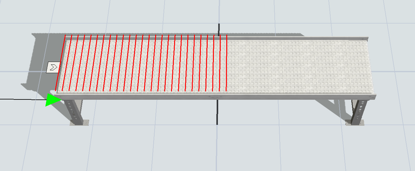
If you see this in your model, it is an indication that the model is improperly configured. The way to fix it is by having some logic that will change the speed so that the maximum flow rate of the receiving conveyor matches the flow rate of the entry transfer feeding it.
In mathematical terms, given the equations above, you're assuming maximum flow:
$\large{F_{max} = D_{max} W S} = \Large{\frac{W S R}{U_xU_y}}$
In this case, $F_{max}$ is known (the rate of flow into the entry transfer), and you solve for $S$ the speed of the conveyor.
$\large{S} = \Large{\frac{F_{max} U_x U_y}{W R}}$
Generally you would have one short conveyor whose speed you set using this formula, then that conveyor can feed other conveyors with different settings downstream.
Side Transfers
When working with mass flow conveyors, you can freely snap conveyors to the side as 'side transfers.' However, unlike with standard conveyors, a mass flow conveyor cannot have outflows or inflows in the middle of the conveyor. Mass flow conveyors will simulate flow as if units always enter at the front of a conveyor and always leave at the end of the conveyor. Thus 'side transfers' are just for model-building convenience, so you can snap them together in whatever way is most convenient for building the model, even though their placement along the conveyor does not affect inflow/outflow logic.