Task 1.3 - Adding and Removing Gaps
Task Overview
This tutorial task will demonstrate several methods to both add and remove gaps in between flow items on conveyors.
Using Inline Transfers to Remove Gapping
In the first step, you'll see how changing the angle of the merging conveyor can remove the gapping in between flow items.
Adding Additional Decision Points to Remove Gapping
In the second step, you'll add additional decision points to help the merge controller increase the rate between slug releases.
Using Area Restriction to Add Fixed Gapping
In the third step, you'll learn how to use the pre-programmed Area Restriction picklist to add gaps in between flow items.
Using Area Restriction to Add Variable Gapping
In the last step, you'll use Area Restriction to add gaps in between flow items based on the size of the flow item.
Step 1 Remove the Gaps Between Items in a Slug
Usually the primary reason why you want a slug-building conveyor system is to reduce gaps between flow items, which increases your system's overall throughput. In the model you built in the previous tutorial task, you may have noticed that a small gap appears between each flow item as slugs move onto the merging conveyor during a simulation run. These gaps could reduce the throughput of the system and you might want to try to eliminate them.
In this step, you'll change the 3D layout of the conveyor system so that the merging conveyor is at an angle. You'll learn how to use the Join Conveyors tool to make this process easier.
One thing to be aware of is that even when you change the angles of the merging conveyors in your simulation model, your conveyors might still put small gaps in between the flow items. In this case, it could be caused by your angle settings on the transfer objects connecting the two conveyors. Your angle settings will determine whether FlexSim treats a transfer like a side transfer or an inline transfer. See Working With Transfer Objects for more information.
In order to prevent possible problems, you'll also create a new global transfer type that increases the Max Angle property in this step. This property increases the threshold for which transfers are treated as inline transfers. This last step isn't necessary but is useful to be aware of when troubleshooting your own merging conveyor systems.
To create this conveyor system:
- Click the merging conveyor to select it. Move the conveyor head (the right end) so that the conveyor is roughly at a 60 degree angle.
- Reposition the ends of the slug-building conveyors so that they nearly touch the merging conveyor. You might also want to reposition the sink and the decision point on the merging conveyor.
- Click the Join Conveyors tool in the Library to enter joining mode. Click the first slug-building conveyor and then click the merging conveyor lane (slightly to the right of the first conveyor) to create a curved connection between the two conveyors.
- Repeat this step for each slug-building conveyor.
- Open the Toolbox. Click the Add button
 to open a menu.
Point to Conveyor System, then click
Transfer Type to open the transfer properties window.
to open a menu.
Point to Conveyor System, then click
Transfer Type to open the transfer properties window. - In the name box at the top, change the transfer type name to SlugTransfer.
- In the Max Angle box, type 60 to increase the angle.
- Press the OK button to save the changes. Notice that the SlugTransfer type now shows up in the Toolbox (under Conveyor System, then Transfer Types).
- Click the transfer between the diverting conveyor and the merging conveyor to highlight it.
- In Properties, click the Transfer Type menu and select SlugTransfer.
- Repeat steps 9-10 for each diverting conveyor.
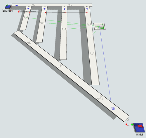
![]()
Run the simulation model. Now the flow items should smoothly transfer without any gapping.
Step 2 Increase the Rate at Which Slugs Are Released
At this point in the simulation model, there are still fairly large gaps between the various slugs as they merge onto the conveyor. In this step, you'll learn a few tricks to increase the rate at which slugs are released by reducing the gapping even more.
One of the ways you can increase the rate at which slugs released is to increase the number of decision points on the conveyor and connect them to the merge controller. Increasing the decision points gives the system more sensors to gauge where slugs are on the merging conveyor line and whether there is enough room to release a slug. The merge controller will then be able to release slugs more frequently. You'll also use the round robin if available strategy to increase the rate at which slugs are released.
To increase the rate at which slugs are released:
- Drag out 3 Decision Points and add one beside every exit transfer on the merging line.
- For clarity, rename the decision points on the merging conveyor as follows:
- Create a port connection (A-connect) from the Merge Controller to each new Decision Point.
- Click the Merge Controller to highlight it.
- In Properties under the Merge Controller tab, click the arrow next to the Release Strategy and select Round Robin If Available.
- Click the Source to highlight it.
In Properties, under the Source section, change the
Inter-Arrivaltime to
2.5.
| Decision Point | New Name |
|---|---|
| The decision point closest to the end of Slug1 | Point1 |
| The decision point closest to the end of Slug2 | Point2 |
| The decision point closest to the end of Slug3 | Point3 |
| The decision point closest to the end of Slug4 | Point4 |
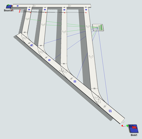
Run the simulation model. The slugs should now release slightly faster than they did before, reducing the gap between items. Also, now your throughput has nearly doubled.
Step 3 Add Gaps Between Items After the Merge
Now that the items have been sorted by their product type and merged onto a single conveyor, you'll add some gapping to the merging conveyor line so that the flow items have standardized spaces in between them.
In this step, you'll create a conveyor at the end of the merging conveyor. Then, you'll add two photo eyes to the gapping conveyor. On each photo eye, you'll use the Area Restriction picklist options to add a gap in between flow items that is equivalent to the gap between the photo eyes.
To create this gapping logic:
- Disconnect (press and hold the Q key) the Sink from the merging conveyor.
- Add a straight conveyor running perpendicular from end of the merging conveyor. Make it fairly long in length.
- For clarity, rename this conveyor GappingConveyor.
- Use the Join Conveyor tool to connect the merging conveyor to the gapping conveyor.
- Move the Sink to the end of the gapping conveyor and connect it to the conveyor using an input/output connection (A-connect).
- Drag 2 photo eyes from the Library and position them near each other in the middle of the conveyor.
- Create a port connection (A-connect) between the two photos eyes.
- Click the upstream photo eye to highlight it.
- In Properties, under the Photo Eye section, clear the Require Gap to Clear checkbox.
- In the Triggers section, click the
Add button
to open a menu. Select On Block.
- Next to the On Block trigger, click the
Add button
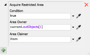
to open a menu. Point to Area Restriction and select
Acquire Area.
- You'll use the default settings, so merely confirm that the settings match the following image:
- Click off of the popup to apply and save the changes.
- Click the downstream photo eye to highlight it.
- In the Triggers section, click the
Add button
to open a menu. Select On Clear.
- Next to the On Clear trigger, click the
Add button
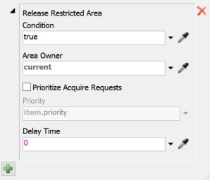
to open a menu. Point to Area Restriction and select
Release Area.
- You'll use the default settings, so merely confirm that the settings match the following image:
- Click off of the popup to apply and save the changes.
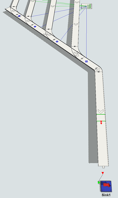
Reset and run the simulation model. The photo eyes should add a small gap between the flow items.
Step 4 Add Variable Gapping
Imagine you wanted to add gaps of varying size in between items. For example, imagine that rather than having a fixed item gap, the size of the gap was determined by the size of the flow item instead. This step will demonstrate how to add that kind of variability to the gapping.
You'll start by setting the source to create flow items with variable sizes. Then, you'll remove one of the photo eyes, and set the remaining photo eye to use both the Acquire Area and Restricted Area picklist options. You'll set the delay time on the release area picklist to base the time on the x-size of the flow item.
To create this variable gapping logic:
- Click the Source to highlight it. In Properties, under the Triggers section, find the On Creation trigger you made previously.
- Next to the On
Creation trigger, click the Edit Properties button
 to open the picklist
properties.
to open the picklist
properties. - Click the Add button
at the bottom of the properties window.
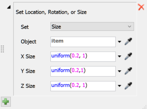
Point to Visual, then select Set
Rotation, Size, or Location.
- Click the Set menu and select Size.
- In the X Size box type
uniform(0.2,1). Type the same thing in the Y Size and Z Size box. - Right now you have two photo eyes on your gapping conveyor. Delete the second one (the downstream one).
- Click the remaining photo eye to highlight it. In Properties, find the Triggers section.
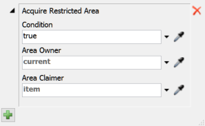
- Next to the
On Block trigger, confirm that this trigger is using the
Acquire Restricted Area picklist option. Click the
Edit Properties button
to open the picklist
properties.
- In the Area Owner box, type
current. Then close the box to save the changes. - Add an On Clear trigger. Next to the new trigger,
click the Add button
to open a menu. Point to
Area Restriction, then select
Release Area.
- Click the arrow next to the Delay Time box to open a menu. Select Time to Convey Item X Size from the menu.
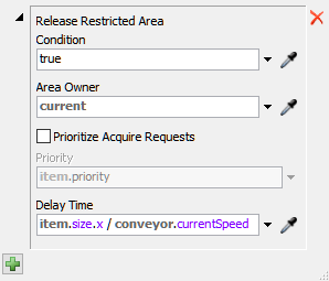
Reset and run the simulation model. The items with smaller widths will have smaller gaps than items with larger widths.
Step 5 Control the Merge With Process Flow
In this step, you'll use a template in the Process Flow tool to reduce gapping and improve the overall throughput in the system. Process Flow templates are pre-built process flows that act as a starting point for creating your own custom logic for 3D objects. These templates are self-documented, which means that each template includes detailed, step-by-step explanations of how the logic works. You can use the default logic in the template or modify the template to make your own custom logic.
In this step, you'll learn how to link a merge controller to a merge controller process flow. When you first open the merge controller process flow, you'll see a section titled How-To. This section gives instructions about how to link a merge controller to the template. This tutorial will skip some of the processes listed in the template's description (because you've already done them) and will do some of the steps out of order, but the basic process will be roughly the same.
First, you'll attach the merge controller to the process flow. Then, you'll set the target gap between slug lanes in the template's process flow variables. (See Process Flow Variables for more information.)
To create this process flow:
- On the main toolbar, click the Process Flow button to open a menu. Point to Add an Object Process Flow, then select Gap-Optimizing Merge Controller.
- Click a blank area of the process flow to ensure nothing is selected.
- In Properties in the Process
Flow Instances group, find the Attached Objects
(instances) property. Click the Sampler button
 to enter sampling mode.
 - Click the Merge Controller in the 3D model to sample it. It should now be listed as one of the attached objects in the process flow.
- In Properties under the
Process Flow Variables group, find the
Target Merge Gap box. Change the target gap to
0.75. - In the 3D model, delete the photo eye on the gapping conveyor.
- Delete the following decision points on the merging conveyor:
- Point1
- Point2
- Point3
- Click the Merge Controller to highlight it.
- In Properties, under the Merge Controller section,
in the Release Strategy box, delete all text and type
0. - Click on the Source to bring up its Properties on the right.
- Under the Source section, change the
Inter-Arrivaltime to
1.5.
Reset and run the simulation model. Now the gap between slug releases is even smaller, increasing the system's throughput even more:
Conclusion
Now that you've learned some of the techniques for adding and removing gaps from conveyor systems, it's time to move onto working with other kinds of systems. In the next tutorial task, you'll learn how to create power and free conveyor systems. Continue on to Tutorial Task 1.4 - Power and Free Systems.