Connecting to PLCs or simulators of Siemens S7 product family
Overview
Emulation module makes FlexSim able to connect to PLCs or PLC simulators of Siemens S7 family.
Several steps are necessary to build a fully functional example:
- Create a TIA Portal project.
- Write the PLC code, compile it and download it to a real or simulated PLC.
- Prepare a FlexSim model and connect it to the PLC.
- Test the model with S7 connection.
- Test the model with PLCSIM Advanced connection.
Step 1 Create a TIA Portal project
In this tutorial TIA Portal v16 will be used.
Open TIA Portal and select Create a new project command:
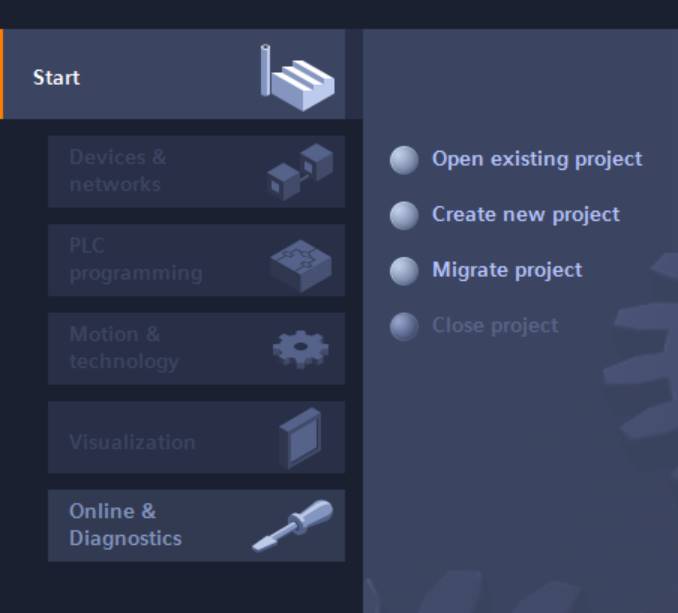
Create a new project and call it “tutorial”, then open the project view.
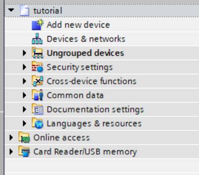
Once the project is created, right click on project name and click on
the “Properties” menu item.
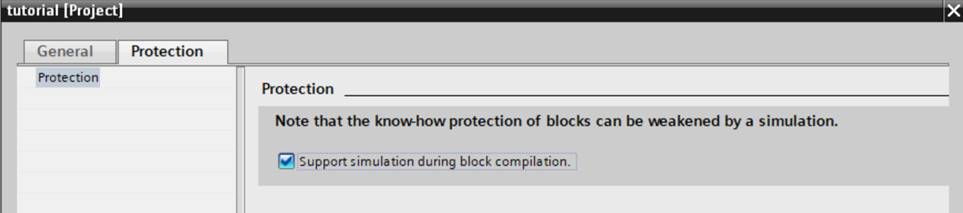
Select the "Protection" tab, then check the “Support simulation during
block compilation” and save.
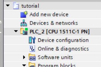
After the project is configured for simulation, then add a new device: in this tutorial a CPU 1511C-1 PN will be used.
To add this device:
- Select "Add new device" from the project view
- Select "Controller" and browse to SIMATIC S7-1700 then CPU 1511C-1 PN and finally select 6ES7 511-1CK01-0AB0.
- This wil add a
Select CPU will be added to the project:
Some configurations should be set on the so added device, to make it suitable with simulation:
- Right click on the CPU and select the “Properties” item.
- Check if the IP address in the“PROFINET interface [X1]” fits with your network configuration.
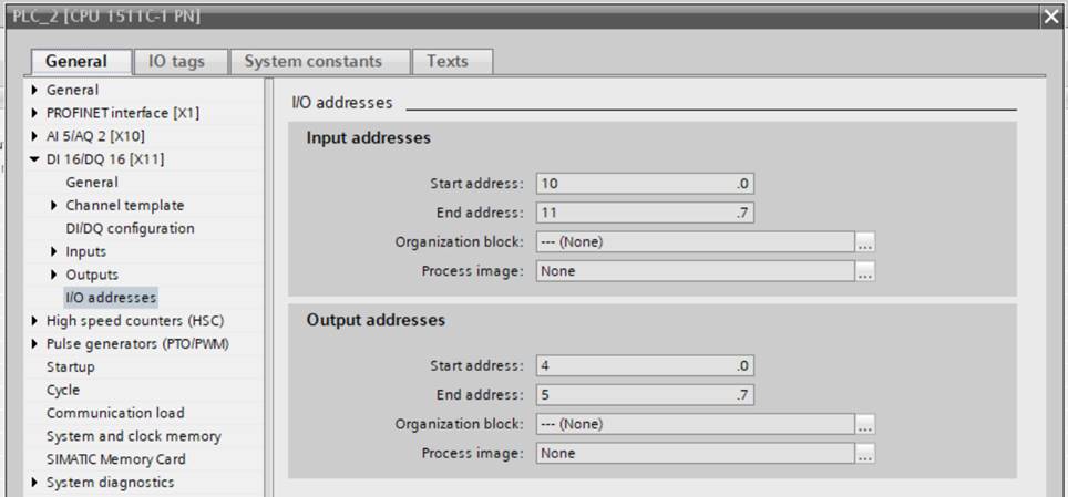
- Go to I/O addresses section for digital I/O and select “none” as Organization lock for both input and output addresses.
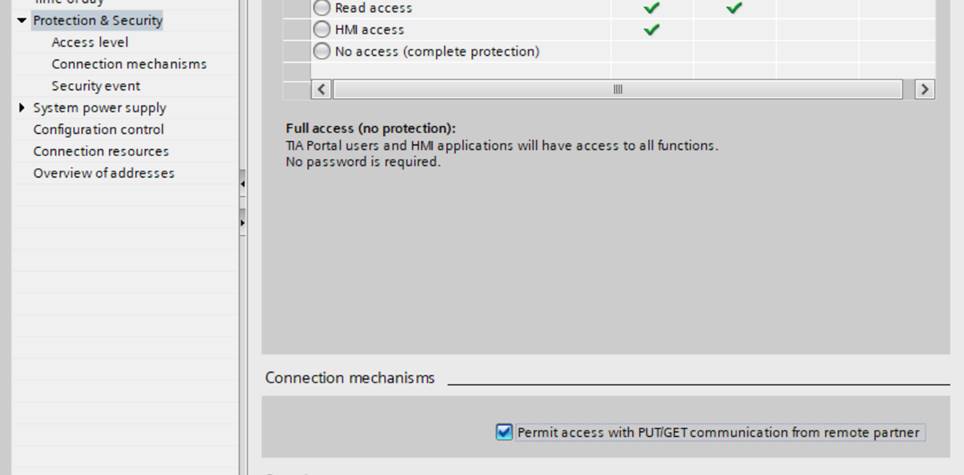
Then go to the “Protection & Security” section and set “Permit access with PUT/GET communication from remote partner”.
Save and close the properties panel.
The project is now ready for simulation.
Step 2 Write the PLC code
Write the PLC code, compile it and download it to a real or simulated PLC.In this tutorial we will realize a simple delayer where a digital input is delayed in output of 1 seconds.
In details, our system will have 1 boolean in and 1 boolean out.
The Boolean output is commonly set to 0, but when the input switches to 1 the output switches immediately to 1 and goes back to 0 after 1 second.
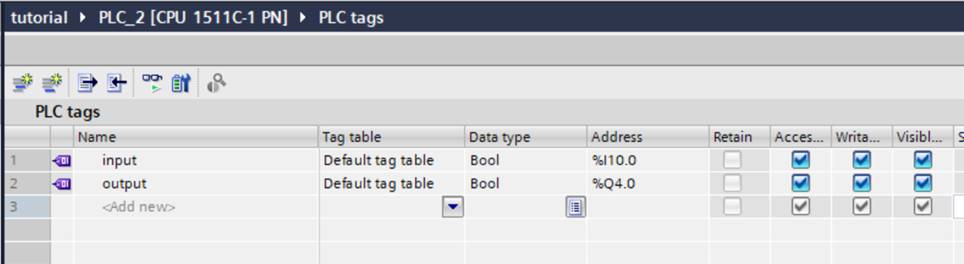
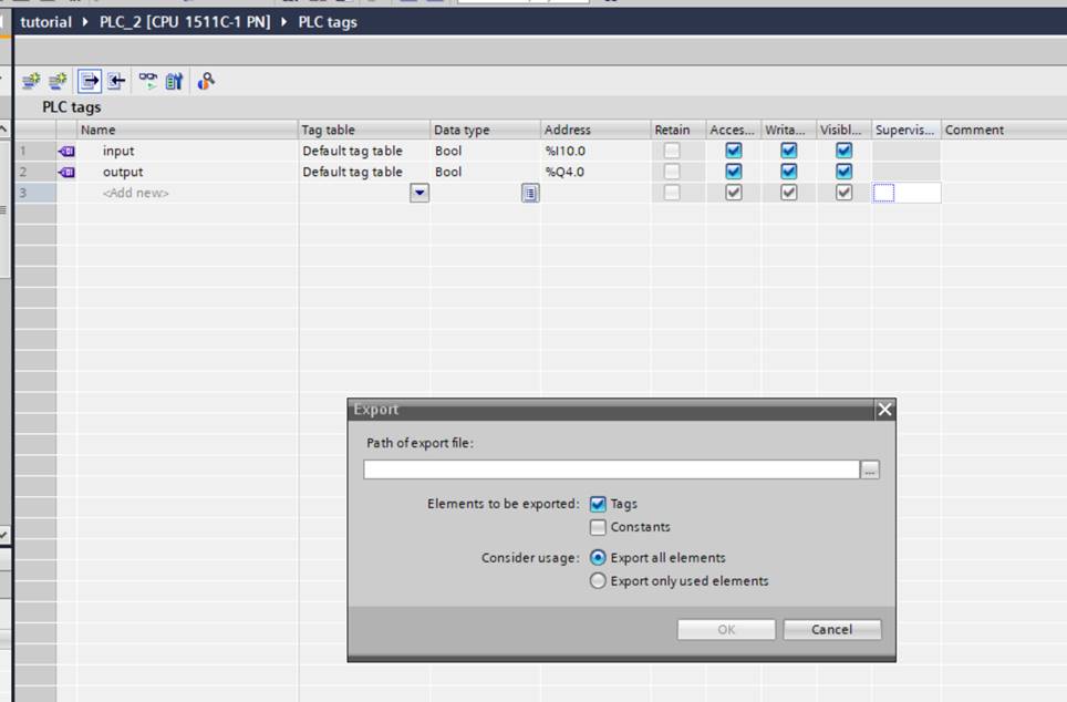
The first operation to do is defining input and output.
Go to the “PLC Tags” section of the CPU and the double click on “Show all tags” item. Then define two tags, “input” and “output”, according with the following table.
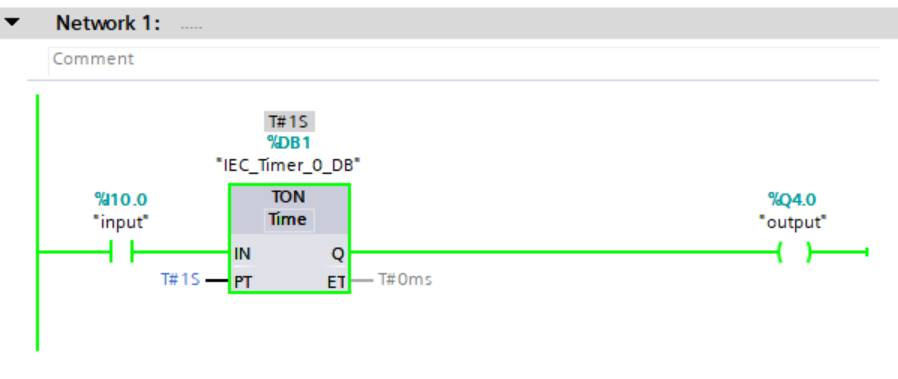
In this program block, when the input goes to 1, the output is set at 1
too with a delay of 1 second.
Compile it using the “Compile”button of the toolbar.
In this tutorial we will interface FlexSim with the PLCSIM Advanced, to
demonstrate both S7 and PLCSIM Advanced connections, so we will download
the code on a PLCSIM Advanced instance.
S7 connections can be used in the same way if the code is downloaded to
a real 1511-1 PN device.
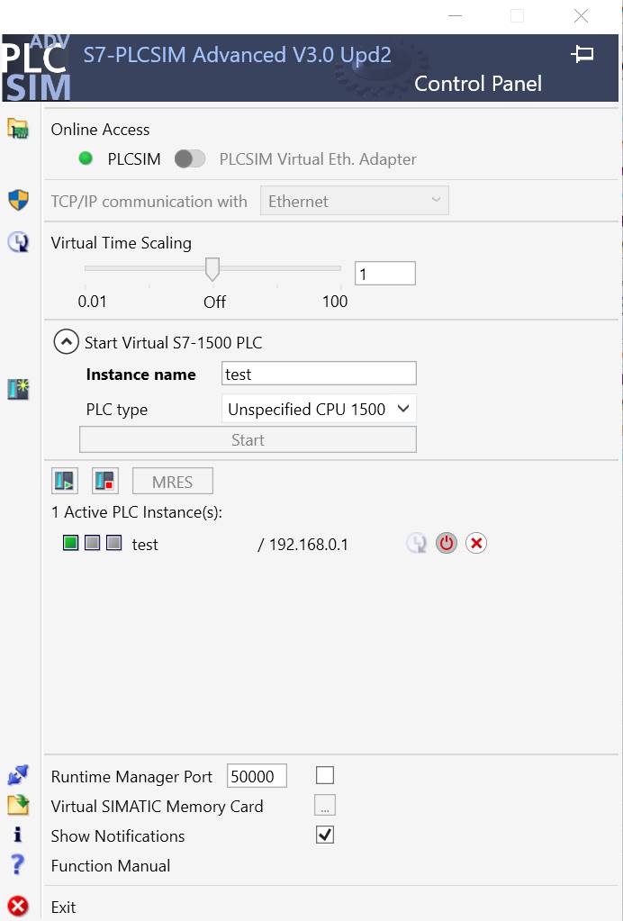
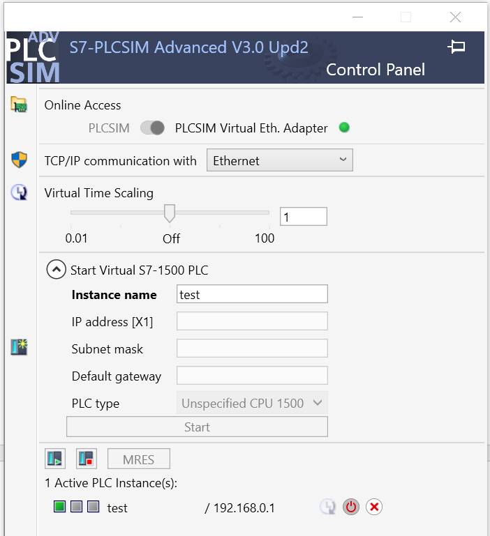
Create an instance named test on PLCSIM Advanced, and download the
compiled code to it using the “Download to device” button.
After the download process is complete launch the instance (the colored
widget close to the instance name should turn to green).
The instance can be also automatically launched during the code download
process.
Step 3 Prepare a FlexSim model
Prepare a FlexSim model to connect to the device.The model that we will use for this tutorial represents a really simple production system where a box item is packaged into a tote:
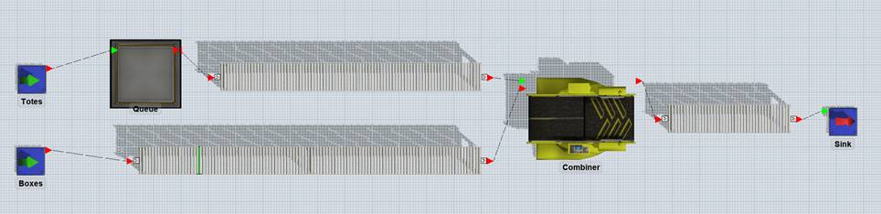
Build a model with two sources (one for boxes and one for totes), a queue for totes and a combiner that will join boxes and totes.>
Connect the elements with conveyors, as represented in the figure above and set conveyor speed to 0.5 m/s.>
Rename the sources to “Boxes” and “Totes”: Totes source is configured to produce 100 totes at time 0, Boxes source is configured to produce a box every 10s.>
A photo-eye is placed on boxes conveyor, approximately 1 meter before totes conveyor start.
Combiner puts a box into a tote in 5 seconds.
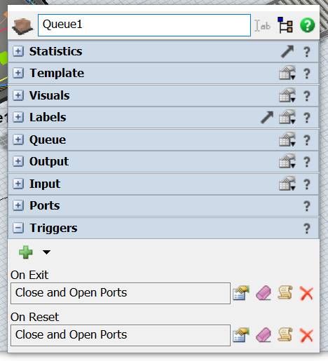
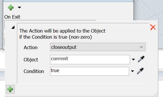
At last, configure the queue to close its outputs at reset and every time that a tote exits from it.
 >
>
Step 4 Test the model with S7 connection
At first, we will create an S7 connection to connect our model directly with the simulated instance hosted into the PLCSIM Advanced.
You must be sure that the instance is up and running before going
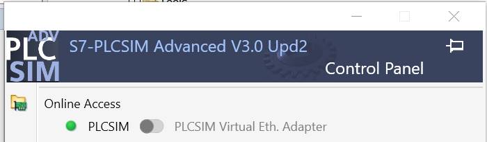
further in this tutorial. It’s also necessary to switch PLCSIM Advanced
access to PLCSIM Virtual Ethernet adapter.
In order to make PLCSIM Virtual Ethernet adapter work, it must be bound
to an IP address on your network. Use the Windows network setting to
assign an address to this virtual interface.
On FlexSim, create a new S7 Connection by adding a new Emulation/Connection from the Tools menu.
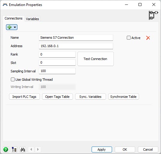
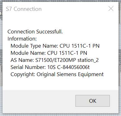
Insert the simulated PLC IP address into the Address field and press “Test Connection” button: if everything is all right you should see a detailed message.
Note that Rank and Slot fields are set to zero: this configuration
depends on the simulated CPU.
Refer to the Emulation manual for all details about these fields.
Remember to set a sampling time suitable for PLC outputs (in our model 50ms is good) and to set the connection status to Active.
When the connection is set, export the Tag table from TIA Portal: go to “PLC tags” item and press Export button.
Save the exported file in your file system:
So exported tags can be imported into the FlexSim model as controls and sensors.
Load the tags file by clicking on the “Import PLC Tags” button on
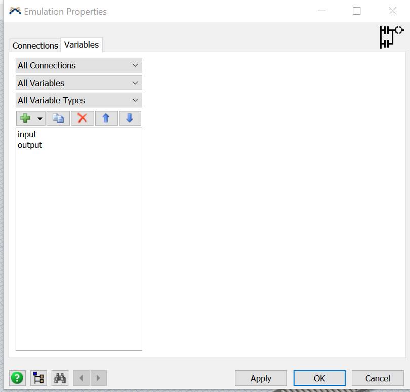
FlexSim S7 Connection panel and then click on “Synchronize vars” button.
This will create two variables called “input” and “output” ad joined to
the PLC Tags.
 >
>
At this point the connection between FlexSim variables and PLC Tags is established. It’s necessary to define how FlexSim models drives PLC input and how PLC’s output is managed by FlexSim as well.
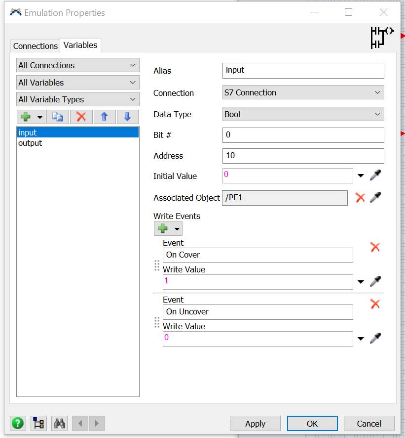
In our model we want that – when a box covers the photoeye – the PLC input is set to 1 and when the PLC output is set to 1 a tote is released from its queue.
The PLC input should be reset to 0 when the photoeye is clear.
To do this, select the input variable, associate it to the photoeye and configure it to write values 1 and 0 when the photoeye is covered and cleared.
Also set the initial value to 0 to reset the PLC input at model reset.
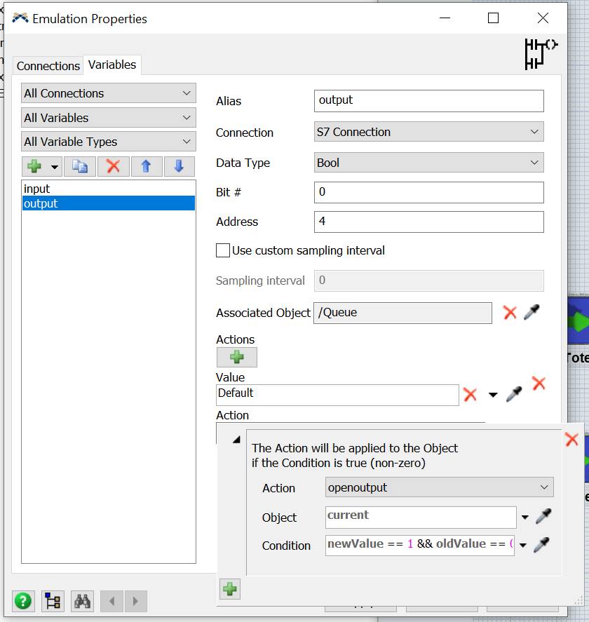
Now select the output variable and associate it to the Tote queue.
Then configure a new action and set the queue open its output when the PLC value turns from 0 (oldValue) to 1 (newValue):
Now the model is fully configured and can be reset and run.
Remember to set the FlexSim’s run speed to 1 to match the timing of the PLC.
You should see a tote exiting the queue 1 second after a box covers the photoeye.
Step 5 Test the model with PLCSIM Advanced connection
In this section we well use the same PLC program of Step 4 and we will build the same automation using the PLCSIM Advanced connection.
In this way we will connect to the PLCSIM Advanced and not directly to the simulated instance on it. In this way we could take advantage from some advanced features, like direct (without export and reimport) listing of PLCTags and instance browsing.
The first step consists in creating a PLCSIM Advanced connection, in the same way we created a S7 connection in step 4.
PLCSIM Advanced can be reached with Softbus or TCP/IP.
Let’s start with a TCP/IP connection, to use the same PLCSIM Advanced
configuration we used in step 4.
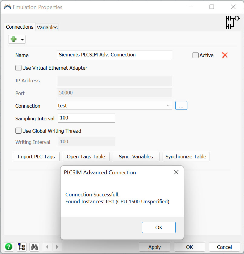
After creating the connection object check the “Use Virtual Ethernet
Adapter” and input the PLCSIM Advanced IP address in the address field.
Note that in this case we are not connecting directly to the instance,
so we don’t have to input the IP address of the simulated instance but
the address of the PLCSIM Advanced software.
If it’s on the same PC, you can put 127.0.0.1 into IP Address field.
After inserting the IP address press the button close to the “Connection” combo box: FlexSim will interrogate the PLCSIM Advanced for running instances and will list them into the combo box itself.
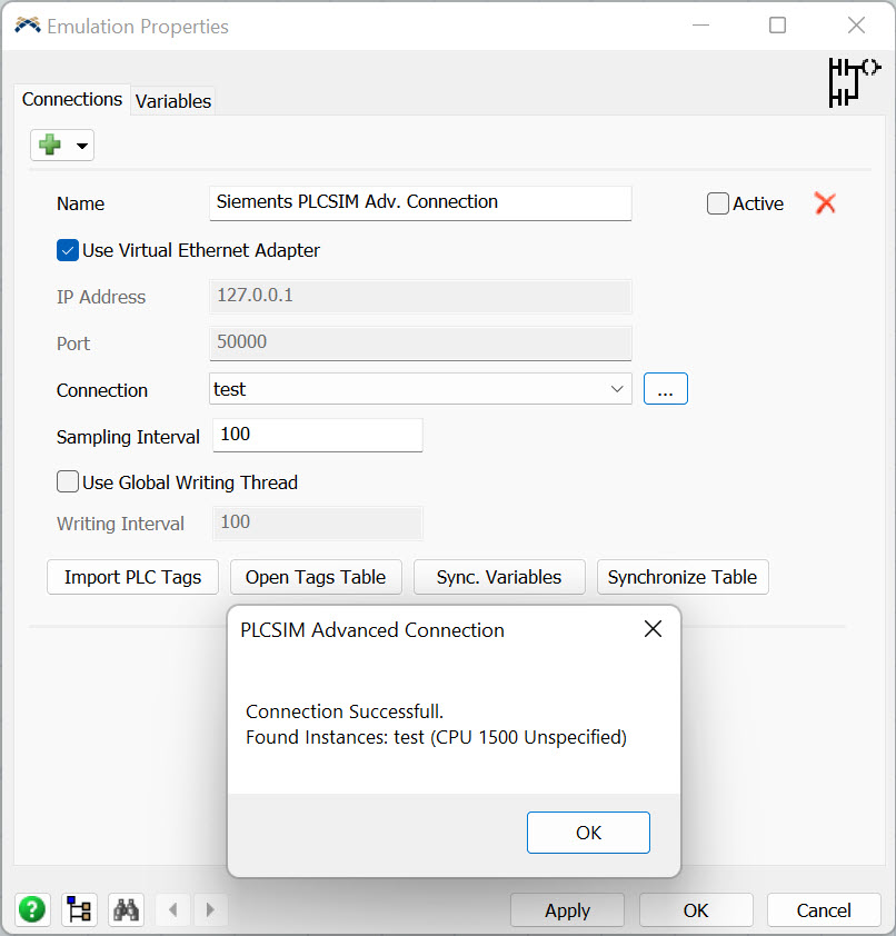
Now select the instance you want to connect to.
Tags import in this mode doesn’t require an export from TIA Portal: it’s sufficient to press “Import PLC Tags” and “Synchronize vars” to populate the Variables tab with the tags declared in the TIA Portal project.
From this point follow the variables management in step 4 to connect your model to the simulated PLC.
If the PLCSIM Advanced is installed on the same machine where FlexSim is installed too, you can connect to it using Softbus protocol.
To do this, select the “PLCSIM” switch into Online Access section of PLCSIM Advanced interface and uncheck the “Use Virtual Ethernet Adapter” on connection panel.
After connecting to the PLCSIM Advanced in this way, all other steps are the same of the Virtual Ethernet Adapter version we saw before