Building AGV Network Logic
Introduction to AGV Network Logic
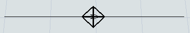
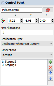
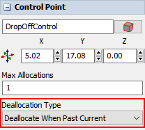
The following image shows an example of a control point on an AGV path:
In addition to the AGV process flow template, AGV control points are the key to creating the logic and functionality of AGV networks:
- AGVs need to be connected to control points in order to enter and exit the AGV network
- When an AGV passes over a control point, that control point can give the AGV instructions about which control point should be its next destination (a pick up point, a drop off point, another control point where the AGV will look for work, etc.)
- Fixed resources must be connected to control points in order to transport items through the AGV network
- Control points can affect traffic control and help prevent potential collisions or deadlocks
- If you are going to use elevators to transport AGVs to multiple floors, you'll need a combination of control points to handle that logic
The rest of the sections in this topic will explain how to set up the AGV process flow template and how to use control points to build the logic of an AGV network. The sections are presented roughly in the approximate order that you'll set up the logic of an AGV network.
Setting Up the AGV Process Flow Template
You can set up and use an AGV network using only standard logic if needed. However, more complex AGV simulation projects will likely benefit from using the AGV process flow template.
To set up an AGV process flow template:
- On the toolbar, click the Process Flow button to open a menu. Point to Add a Task Executer Process Flow and select AGV to create a new process flow template.
- In the newly created process flow, click a blank area to ensure nothing is selected.
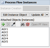
In Quick Properties under the Process Flow Instances group,
find the Attached Objects (instances) box. Click the
Sampler button
 by this box to enter sampling mode.
 - In the 3D model, sample an AGV. It should now show up in the Attached Objects box.
- Repeat the previous steps to add additional AGVs as needed.
After setting up the process flow, you'll still need to set up the rest of the logic for the AGV network, such as creating Next Look for Work loops and setting any fixed resources to use the AGVWork global list as its transport. The rest of these steps are covered in the subsequent sections of this topic.
Types of Control Point Connections
Control points are the basic building blocks of logic in an AGV network. However, the real logic of control points depends on the nature of its connections to other control points and 3D objects. Be aware that control points can connect to more than one object as needed and that you can customize control point behavior to meet your model's needs.
Control points have the following possible connection types:
| Type | Description | Appearance |
|---|---|---|
| Location | Location control points are for connecting fixed resources to an AGV network. Once a fixed resource is connected to a location control point, it can send and receive flow items through the control point. | 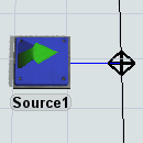 |
| Pick Up Points | Pick up points can be connected to location points to create a specific point where AGVs can load flow items. The location control point will route flow items to those points when it receives them from an upstream fixed resource. | 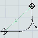 |
| Drop Off Points | Drop off points can be connected to location points to create a specific point where AGVs can unload flow items. The location control point will route AGVs to drop off items at one of those points and then send it to a downstream fixed resource. | 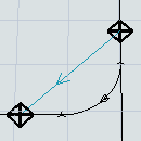 |
| Park Points | Park points can be connected to a control point that has been set as the entry point for an AGV. When the simulation model starts, an AGV will be sent to this park point and the AGV will enter the network at this point. AGVs can also charge their batteries at park points when their batteries are running low. | 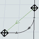 |
| Look for Work | Although seldom used, these kinds of connections can act as a kind of decision point where an AGV could decide where to go next to look for work. Imagine that you have a loop of control points that may or may not contain work for an AGV. If there is work to be done on this loop, the AGV should be routed to those control points. If there is not available work, the AGV should skip the loop and continue on in the AGV network. You would create look for work connections from the control points inside the loop that connect back to the upstream control point where the AGV will check for work. Be aware that these kinds of control points aren't necessary if you are using the AGV process flow template. | 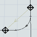 |
| Next Look for Work | You'll need to have a series of Next Look for Work connections in your AGV network if you want to create a system in which AGVs loop around the system looking for work. These connections tell AGVs where their next destination should be if they are looking for work. When an AGV reaches the upstream control point, it will check for work at that control point. If there is no available work, it will travel to the downstream control point. | 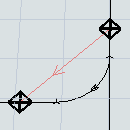 |
| Elevator Floor | See Adding Elevators to AGV Networks for more information. | |
| Elevator Redirect | See Adding Elevators to AGV Networks for more information. | |
| Elevator Entry | See Adding Elevators to AGV Networks for more information. |
Adding Control Points to a Path
To add a control point to a path:
- In the Library under the AGV group, drag a Control Point into the model.
- Position the control point so that it is over an AGV path. When it connected to an AGV path, the control point will look like a diamond with crosshairs, as shown in the following image:
Connecting Fixed Resources to the AGV Network
The only way items can enter or exit an AGV network is through a fixed resource that is connected as a location to the AGV network. This section will explain how to connect fixed resources and create pick up or drop off points.
Connecting Fixed Resources
To connect a fixed resource to a control point:
- Press and hold the A key to enter connection mode. When you are in connection mode,
your mouse pointer will change to a plus sign with a chain link symbol next to it:

- Click the fixed resource you want to connect to a control point. You will notice as you move your mouse that a yellow line will appear between the object you clicked and your cursor.
- Hover over the control point so that it is highlighted. Click the control point to open a menu. Select Location. A blue line will appear to show that the fixed resource is now connected to the control point.
- Double-click the fixed resource to open its properties window. On the
Flow tab, set up the Send To
Port property so that it sends items to the appropriate destination:
- You can use port connections to send the item to its destination. Make sure that the upstream fixed resource is connected to the downstream fixed resource with an input/output port connection (A-connect). Then set the port connection to use whatever flow logic your business system needs. See Overview of 3D Object Flows for more information.
- You can push the item to a list. Make sure that the downstream fixed resource(s) are set up to pull items from the list as well.
- Also on the Flow tab, check the Use
Transport box. In the box next to this checkbox, set up this property to assign
AGVs to transport the item to its destination:
- If you are using the AGV process flow template, you should select Use List and select the AGVWork list that is automatically generated when you use the AGV process flow template.
- If you are using a simple AGV network system with one AGV, use a center port connection (S-connect) to connect the fixed resource to the AGV.
- If you are using multiple AGVs, use a center port connection (S-connect) to connect the fixed resource to a dispatcher. Then, use input/output connections (A-connects) connect the dispatcher to all the AGVs in the system.
When a simulation runs, the fixed resource will hold the item until the AGV reaches the control point it is connected to. The item will immediately appear on the AGV once it has been transferred.
Creating Pick Up Points
As you can see in the previous image, flow items will wait at a connected fixed resource until an AGV transport arrives. Alternatively, you can set up the fixed resource to push flow items to one or more pick up points instead.
To create one or more pick up points:
- Create AGV paths to the pick up points area. If you want, the pick up points area can be on a loop separated from the main AGV network loop or it can be a small offshoot from the main AGV network loop.
- Add control points on the AGV paths where the AGVs should pick up the flow items.
- Press and hold the A key to enter connection mode. When you are in connection mode,
your mouse pointer will change to a plus sign with a chain link symbol next to it:
- Click the control point that is connected to the fixed resource. You will notice as you move your mouse that a yellow line will appear between the object you clicked and your cursor.
- Hover over the control point that will become the pick up point so that it is highlighted. Click the control point to open a menu. Select PickupPoints. A green line will appear to show that the location control point is now connected to the pick up control point.
- Repeat the previous steps as needed to create additional pick up control points.
When a simulation runs, the fixed resource will transfer the item to the pick up point where it will wait for transport by an AGV.
If you've created a separate looping path for the pick up points, the AGV will only travel there if it passes over the location control point and finds available work. If the pick up points are empty, it will not travel on the separate pick up point path and will instead continue to the Next Look For Work point.
Creating Drop Off Points
In the same way that you can create pick up points for AGV transfers, you can also create drop off points for fixed resources.
To create drop off points:
- Create AGV paths to the drop off points area. If you want, the drop off points area can be on a loop separated from the main AGV network loop or they can be small offshoots from the main AGV network loop.
- Add control points on the AGV paths where the AGVs should drop off the flow items.
- Press and hold the A key to enter connection mode. When you are in connection mode,
your mouse pointer will change to a plus sign with a chain link symbol next to it:
- Click the control point that is connected to the fixed resource. You will notice as you move your mouse that a yellow line will appear between the object you clicked and your cursor.
- Hover over the control point that will become the drop off point so that it is highlighted. Click the control point to open a menu. Select DropoffPoints. A light blue line will appear to show that the location control point is now connected to the drop off control point.
- Repeat the previous steps as needed to create additional drop off control points.
When a simulation runs, the AGV will transport the item to the drop off point and then it will immediately appear in the fixed resource.
Connecting AGVs to the AGV Network
In order for an AGV to enter an AGV network, it needs to be connected as a Traveler AGV to a control point on the main AGV network. Choose a control point that is on the main AGV network. It should be close to the area where you want the AGVs to enter.
To connect an AGV to a control point:
- Press and hold the A key to enter connection mode. When you are in connection mode,
your mouse pointer will change to a plus sign with a chain link symbol next to it:
- Click the AGV. You will notice as you move your mouse that a yellow line will appear between the object you clicked and your cursor.
- Hover over the control point so that it is highlighted. Click the control point to open a menu. Select Traveler AGV. A red line will appear to show that the AGV is now connected to the control point. When you reset the model, the AGV will begin traveling from this control point.
- Repeat the previous steps to connect multiple AGVs to control points.
When you reset the simulation model, any AGVs that are connected to this control point will appear on that point. If multiple AGVs are connected to that point, they might overlap on that control point.
Creating Park Points
Park points are locations where AGVs begin when the simulation model first starts running. During a simulation run, an AGV can return to the park point to recharge its batteries if its batteries are running low.
- Before creating a park point, an AGV should first be connected as a Traveler AGV to a control point on the main AGV network. (See the previous section for instructions.)
- Create AGV paths to the park point. Usually, park point paths are small offshoots from the main AGV network loop.
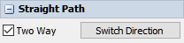
- Click one of the newly created paths to select it. In Quick Properties, check the Two Way check box to ensure the AGV can travel in both directions on this park point.
- Repeat the previous steps to ensure that all park point paths and the paths that join them to the main AGV network are two-way paths.
- Add control points to the AGV paths where the AGVs should park.
- Press and hold the A key to enter connection mode. When you are in connection mode,
your mouse pointer will change to a plus sign with a chain link symbol next to it:
- Click the control point that is connected to the AGV on the main AGV network. You will notice as you move your mouse that a yellow line will appear between the object you clicked and your cursor.
- Hover over the control point that will become the park point so that it is highlighted. Click the control point to open a menu. Select ParkPoints. A dark green line will appear to show that the location control point is now connected to the park control point.
- Repeat the previous steps as needed to create additional park control points. Make sure there is a park point for each AGV in your simulation model.
When you reset the simulation model, AGVs will at first appear on the control point on the main AGV network that the AGVs are connected to. However, once the simulation model begins running, the AGVs will immediately move to a park point.
Creating Next Look for Work Loops
The AGV process flow template implements a somewhat common AGV system in which AGVs travel in a loop around the facility, looking for transportation tasks to work on. In order to create this kind of logic, you need to create a Next Look For Work loop in your AGV network. A Next Work For Work loop is basically a series of control points that are connected to each other in a loop.
When an AGV passes over one of the control points in the loop, it will check for available transport tasks at that location. If it finds an item to transport, it will load that item and take the shortest distance to the item's designated destination. If it does not find an item to transport at that location, it will travel to the next control point in the Next Look For Work loop and check for work at that point. The AGV will loop through all of the connected control points looking for work.
To create a Next Look for Work loop:
- Press and hold the A key to enter connection mode. When you are in connection mode,
your mouse pointer will change to a plus sign with a chain link symbol next to it:
- Click the first upstream control point the AGV will pass over in the Next Look For Work loop. You will notice as you move your mouse that a yellow line will appear between the object you clicked and your cursor.
- Hover over the second control point you want to connect so that it is highlighted. Click the control point to open a menu. Select NextLookForWork. A red line will appear to show that the control points are now connected.
- Repeat this process to add more control points to the loop. Make sure that the last control point gets connected to the first control point to create a loop.
When you run the simulation model, the AGVs will enter the system as soon as a transportation task is available. They will then circulate through the AGV network traveling to each control point in the Next Look For Work loop.
Removing Control Point Connections
To remove a control point connection:
- Click the control point to select it.
- In Quick Properties, click the Connections menu and select the type of connection you want to remove.
- In the box below this menu, click the name of the object to which you want to remove the connection.
- Click the Remove button
 to delete the connection.
Changing AGV Settings
After you've set up the basic logic of your AGV network, you might want to make changes to the way AGVs behave. You can customize the speed at which AGVs travel, their load capacity, their battery life cycle, the amount of time they take to load and unload items, etc. This section will discuss the different properties you can control and where to adjust those settings.
AGV Process Flow Template Variables
If you are using the AGV process flow template, you'll need to enter values for a few of the process flow variables on the AGV process flow:
- With the AGV process flow template open, click a blank area in the process flow to ensure nothing is selected.
- In Quick Properties under the Process Flow Variables group, enter the settings for the following the three process flow variables.
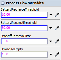
- BatteryRechargeThreshold - Enter the battery percentage
level at which the AGV should stop performing any more work and immediately park and
recharge. If you don't want to simulate battery depletion/recharge, type
-1for this variable. - BatteryResumeThreshold - Enter the battery percentage
level at which the AGV may resume after parking. If you don't want to simulate
depletion/recharge, type
-1for this variable. - DropoffRetrievalTime - If you have added drop off points to your AGV network, the AGV will travel and unload at a drop off point. After it unloads at the drop off point, the AGV will remain at this drop off point before moving the item to the final destination. The amount of time the AGV remains at the drop off point is based on the amount of time you indicate for this variable. This time delay simulates the time it would take for someone to come and retrieve the load from its drop off point.
AGV Network Properties
The AGV network properties can be accessed either from the Toolbox (it shows up as AGV Network) or by clicking on an AGV path and clicking the Network Properties button in Quick Properties.
Using the AGV network properties window, you can set the global speed for all AGVs on the AGV networks, their battery capacities and charging rates, their accumulation behavior, their deallocation behavior, and general visual settings. The following shows two of the more useful tabs on the AGV Network Properties window:
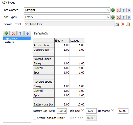
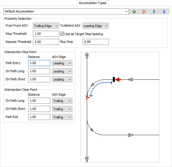
See AGV Network in the reference section for more information about these properties.
TaskExecuter Properties
If you double-click an AGV (which is technically the TaskExecuter object), it will open its properties where you can edit properties such as its capacity, max speed, acceleration, deceleration, etc.
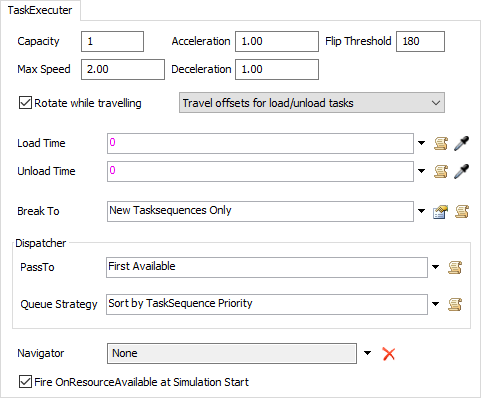
See The Task Executer Tab in the reference section for more information about these properties.
Preventing Collisions and Deadlocks
AGV networks have a sophisticated look-ahead mechanism that can avoid crashes by determining if the next control point on the path is available or not. If it is not available, the AGV will wait at its current control point.
A few key terms to be aware of:
- Allocation - When an AGV is traveling to or occupying a control point, that means the control point has allocated that control point. You could think of it as acquiring that control point so that it can't be acquired by other AGVs. You can set the number of AGVs that can allocate a specific control point at a given time.
- Deallocation - When an AGV releases a control point so that it can be acquired by another AGV. You can set a control point to deallocate when an AGV reaches the next control point or you can set it to deallocate the control point after an AGV has passed over it.
If you run your simulation model and experience collisions or deadlocks, the issue is probably caused by how control points are being allocated and deallocated. This section will explain some of the methods to troubleshoot these kinds of problems.
Adding More Control Points
One simple solution to fixing deadlocks is to add more control points along an AGV path. Having more control points makes it so that AGVs have more opportunities to deallocate quickly.
Changing Deallocation Types
By default, control points are set to deallocate when the AGV reaches the next control point. You can change a control point's deallocation type to make it less strict:
- Click a control point to select it.
- In Quick Properties click the Deallocation Type menu and select Deallocate When Past Current.
Adding Control Areas
Adding a control area around a portion of an AGV model can also help to prevent AGVs from colliding with each other. Control areas will restrict access to an area of the AGV network so that only a set number of AGVs can occupy that area at a time. By default, only one AGV can occupy the area at a time, but you can change the number of AGVs that can access the area in the control areas properties if needed.
To add a control area:
- In the Library in the AGV group, click Control Area to enter control area building mode.
- Place your cursor outside the top right corner of the portion of the AGV network where you want to add the control area. Click to begin drawing a control area box. Draw the control area box around the portion of the AGV network you want to restrict.
- Press Esc to exit control area building mode.
- Click the control area and use the sizer arrows if you need to resize the control area.
- While the newly added control area is selected, you can edit its properties in the Quick Properties panel if needed.