Task 1.3 - Add A* Navigation
Task Overview
In this tutorial task, you'll add some additional locations and staff to the health care clinic model. Then, you'll learn how to use A* navigation to prevent the patients and staff members from walking through objects and the floor plan walls. With A* navigation, you can designate where the patients and staff members can walk and where they cannot.
After that, you'll build more of the patient track for the health care clinic model to get some additional practice using the FlexSim Healthcare objects and activities.
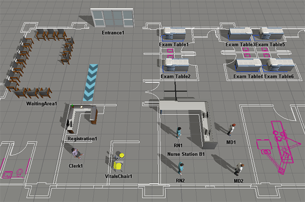
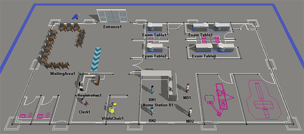
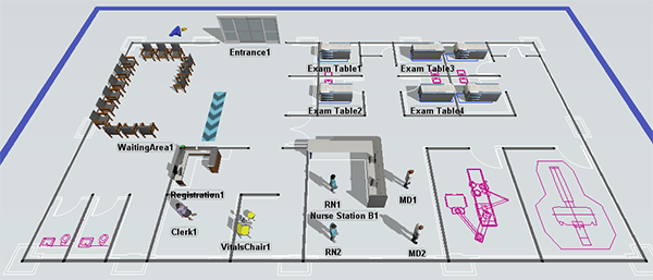
When you're finished, your simulation model should look similar to the following image:
Step 1 Add Additional Locations and Staff
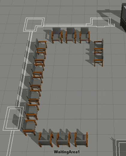
In this step, you'll build out a little more of the 3D objects in the health care clinic by adding some more FlexSim Healthcare locations and staff objects to the model. In this step, you'll see what it's like to add several copies of the same object at the same time using the Create Objects mode.
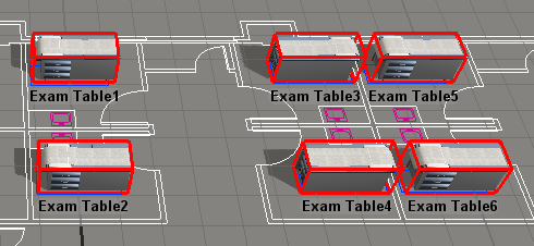
When you're finished, your model should look similar to the following image:
To add these additional 3D objects:
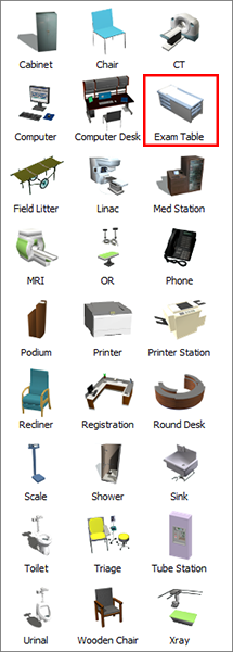
- In the Library under the Healthcare group, click the
Location object to open a menu. Click (don't drag) the
Exam Table to enter Create Objects mode. Your mouse pointer
will change to the Create Objects icon
 when you're in Create Objects mode. Click the area in the model where you want to add
the first exam table. (Use the image at the beginning of this step to guide you on the
placement of objects.)
when you're in Create Objects mode. Click the area in the model where you want to add
the first exam table. (Use the image at the beginning of this step to guide you on the
placement of objects.) - While still in Create Objects mode, click inside the model to add a second Exam Table.
- Repeat the previous step to add more Exam Tables until there are a total of 6 tables in the model. Press Esc or right click to exit Create Objects mode.
- Click Exam Table 3 to select it. In Quick Properties,
change the Z-rotation
 to
to
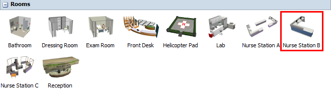
180.00. Repeat this step for Exam Table 4 as well. - In the Library under the Healthcare group, click the Prop object to open a menu of prop objects. Drag a Nurse Station B (under the Rooms group) into the 3D model.
- Click Nurse Station B1 to select it. In Quick
Properties, change the Z-rotation to
90.00. - In the Library under the Healthcare group, click the Staff object to open a menu of staff objects. Drag an MD (Female) and an MD (Male) into the model.
Check to make sure your simulation model looks similar to the image at the beginning of this step.
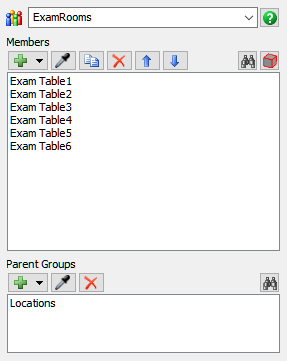
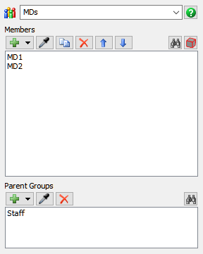
Step 2 Create Additional Object Groups
Since you added several new 3D objects to your simulation model in the previous step, you need to create object groups for those new objects in order to make your model scale well. In this step, you'll create a location group named ExamRooms for the new exam tables and you'll create a staff group named MDs for the MD staff members.
To create additional object groups:
- Press and hold down the Shift key while using your mouse to draw a box around all six of the new ExamTable objects you added to your model in the previous step. A red box will appear around the ExamTables to show they are selected.
- Right-click ExamTable1 to open a menu. Point to Location Groups, then select Add to New Group to open a group properties window.
- In the name box, delete the current text and rename the group ExamRooms.
- Confirm that all six of the ExamTables are members of the group. Close the group window.
- Press and hold down the Shift key while clicking a blank area in the 3D model with your mouse to de-select the ExamTables.
- In the 3D model, press the Ctrl button and click MD1 to select it. While still pressing the Ctrl key, click MD2 to select it as well. Right-click MD1 to open a menu. Point to Staff Groups, then select Add to New Group to open a group properties window.
- In the name box, delete the current text and rename the group MDs.
- Confirm that MD1 and MD2 are both listed as a member and that Staff is listed as the parent group. Close the group window.
- Press and hold down the Shift key while clicking a blank area in the 3D model with your mouse to de-select the MDs.
Consider saving your simulation model at this point.
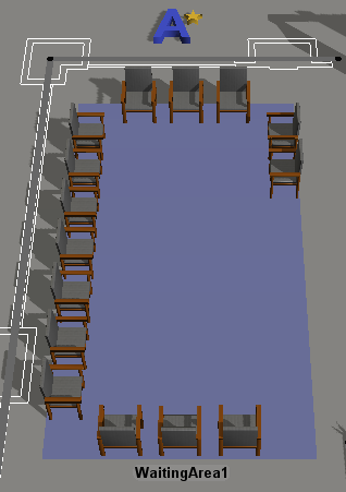
Step 3 Add A* Dividers
In this step, you'll add some A* dividers to the model. A* navigation is a tool that calculates the most logical path a person should use when walking from one object to another. You can place dividers to prevent a person from walking through an area that they shouldn't walk through (such as walking through an object or the wall of a room). The A* Navigator will take these dividers into account when calculating the best path for a person to travel. See Working With A* Navigation for more information.
When you're finished adding the dividers, the model will look similar to the following image:
Because it can sometimes be difficult to view the barriers against the dark gray model background in the FlexSim Healthcare environment, the following images shows the dividers in the standard environment for reference:
To add A* dividers:
- Make sure the 3D model is open and active. In the Library under the
A* Navigation group, click a
Divider object to enter Create Dividers mode. Your mouse
pointer will change to the Dividers icon
 to show that you are in Create Dividers
mode.
to show that you are in Create Dividers
mode. - Find the position in your simulation model where you want to place the beginning corner of a divider. When you click that position in the model and start moving the mouse pointer in a different direction, you'll notice that it begins creating a divider. Reposition the mouse pointer until the divider's end is at the approximate length, angle, and radius you want it to be relative to the start. Click the mouse again to finish creating the divider. Press Esc to exit Create Divider mode.
- These dividers will act as walls in the simulation model. Start by creating the outer walls on the floor plan (the ones surrounding the whole building). If you need to move or resize a divider, click the end points and drag them to a different position.
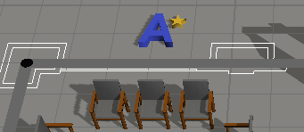
- Notice that when you added the dividers, an A* Navigator was automatically added in the center of your simulation model. (It looks like a blue A with a golden star next to it.) Drag the A* Navigator to a different area, placing it somewhere outside the floor plan.
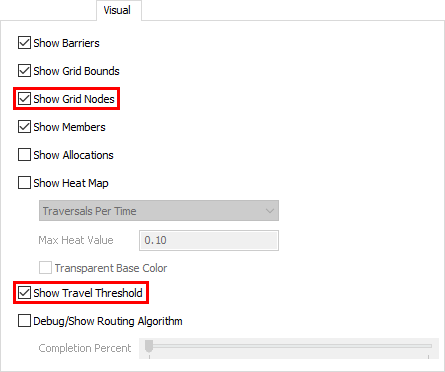
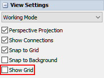
- Before adding dividers to the interior walls of the floor plan, double-click the A* Navigator to open its properties window. On the Visual tab, check the Show Grid Nodes and Show Travel Threshold checkboxes. Click the OK button to save changes and close the window.
- Click a blank area in the 3D model so that nothing is selected. In Quick Properties under View Settings, clear the Show Grid checkbox.
- Click the Reset button on the simulation control bar to ensure that the visual changes take effect.
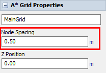
- Click the A* Grid (the large blue bar that surrounds the A* dividers) to select it.
- In Quick Properties in the Node Spacing box, delete the
current number and type
0.50instead. Notice that the dividers and grid lines will become smaller. - Click the Reset button on the simulation control bar to ensure that the visual changes are evenly applied to the model.
- Add more dividers for the interior walls of the building. Don't worry about putting the dividers exactly over the floor plan's walls. It's more important to try to put dividers in between the yellow A* grid lines if possible. These dividers will prevent movement from one point on the grid to another so it will work better if placed in between the grid rather than over it.
- Now that you've added dividers, you don't need the yellow gridlines any more. Double-click the A* Navigator to open its properties window. On the Visual tab, check the Show Grid Nodes checkbox. Click the OK button to save changes and close the window.
- Click the Reset button on the simulation control bar to apply these visual changes.
Now that you've added A* dividers, it's time to add the 3D objects in the model to the A* navigation system. You'll add the objects in the next step.
Step 4 Connect 3D Objects to the A* Navigator
In this step, you'll connect most of the model's objects to the A* Navigator. By connecting the 3D objects to the A* system, it will create a small area of space around the objects that staff and patients will not be able to walk through. You'll also learn how to check 3D object's travel thresholds in order to prevent any strange behavior when the 3D objects are using the A* navigation system.
To connect the 3D objects to the A* Navigator:
- Press and hold the A key to enter connection mode. When you are in connection mode,
your mouse pointer will change to a plus sign with a chain link symbol next to it:

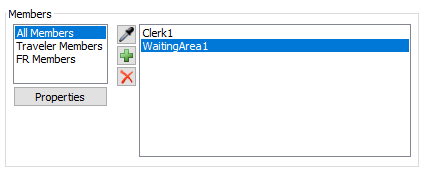
- Once you are in connection mode, click the A* Navigator. Click WaitingArea1 to create a connection between the two objects.
- These next steps will demonstrate another method for adding members to the A* navigation system. Double-click the A* Navigator to open its properties window.
- On the Setup tab in the Members group, make sure that All Members is selected as the current member view.
- Click the Sampler button
 to enter sampling mode.
 - In the 3D model, sample the Clerk1 staff member. Notice that it now appears as a member in the members list.
- Using your preferred method, add the rest of the 3D objects to the A* navigation
system (including staff objects) EXCEPT the following objects:
- Entrance1
- WaitingLine1
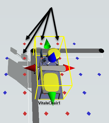
- Click the VitalsChair1 to select it. Notice that you can now see the chair's travel threshold, represented by several red dots surrounding the chair. Depending on how your chair is placed, there might also be blue dots surrounding those dots.
- Check to ensure that the none of the red travel threshold dots go beyond the dividers. (It is fine if the blue dots extend beyond the dividers.) For example, the following image shows a chair's red travel threshold that extends past a divider in standard mode:
- Drag the VitalsChair1 so that it is a little further away from the divider and none of the red travel thresholds extend beyond the divider. Be aware that there will also not be any problems if the red travel thresholds are exactly inside a divider.
- Repeat the previous steps with all of the Exam Tables to ensure their red travel threshold dots do not extend beyond each room's walls.
- You might want to make sure the WaitingArea1 is right up against the surrounding dividers so that patients and staff won't try to walk behind them or try to squeeze into small gaps between the objects.
- If you decide to place a divider in front of the Registration1 object, you might want to make sure that the desk's travel threshold extends past the divider so that the patients can reach it without having to go around the divider.
- You might also want to put barriers around the Nurse Station B1 to keep staff from walking between the gaps. Don't forget to check its travel threshold as well.
- If you would like to turn off the visual guides for the A* Navigation system, double-click the A* Navigator to open its properties window. On the Visual tab, clear all the checkboxes.
Reset and run the simulation:
Now when you run the model, the patients and the RNs no longer walk through objects or walls. Notice that the RN walks around the desks and the walls in the floor plan while traveling to the patient vitals area with the patient.
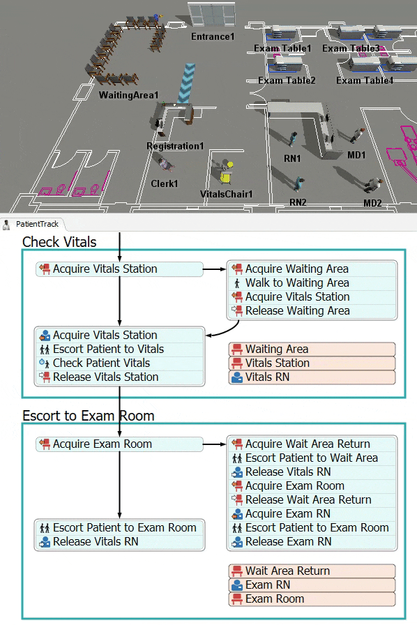
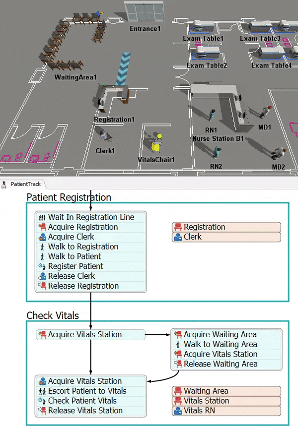
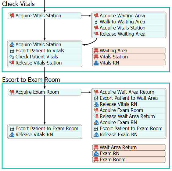
Step 5 Add an Escort to Exam Room Phase
In this step, you'll add another activity set to the patient track. This activity set is called Escort or Wait Area. You'll use this activity to have a nurse escort the patient to an exam room if one is available. You'll need to make a few customizations to this activity set so you'll add and remove a few activities in this step. These customizations will make it so that the nurse escorts the patient back to the waiting area rather than the patients returning to the waiting area on their own.
When you're finished, the process flow will look similar to the following image:
For now, you'll merely add and connect these activities to the process flow. You'll edit the properties to add logic in a later step.
To add and connect these activities:
- Make sure the PatientTrack process flow is open and active.
- From the Library under HC Activity Sets, add an Escort or Wait Area activity set to the process flow.
- Rename this shape container as Escort to Exam Room.
- Delete the Acquire Staff activity on the left.
- Delete the second block of stacked activities on the right (the one with four activities).
- Delete all the connectors inside this shape for now.
- In the Library under the HC Sub Flows group, add an Escort Patient activity and insert it after the Acquire Wait Area activity in the stacked block on the right.
- In the Library under the HC Resources group, add a Release Staff activity and insert it after the Escort Patient activity in the stacked block on the right.
- Press and hold the Ctrl key. In the activity block on the right of this shape, click the Walk to Wait Area activity and move it away from the stacked block to another space in the process flow. Delete the Walk to Wait Area activity.
- Repeat that process to delete the Process and Release Location activities from the stacked block on the left.
- Click the stacked block on the left to select it. (It should have two activities: an Escort Patient and a Release Staff activity.) Press Ctrl+C to copy the stacked block. Press Ctrl+V to paste the stacked block.
- Add the newly copied stacked block to the end of the stacked block on the right.
- Rename the activities and shared assets as follows:
- Create a connector from the Release Vitals Station activity in the Check Vitals shape to the Acquire Exam Room activity on the left.
- Create a connector from the Acquire Exam Room on the left to the Escort Patient to Exam Room activity on the left.
- Create a connector from the Acquire Exam Room on the left to the Acquire Wait Area Return activity on the right.
- Click the first Acquire Exam Room activity to select it. Confirm that connector 1 is going to the Escort Patient to Exam Room activity and that connector 2 is going to the Acquire Wait Area Return activity. If not, delete the connectors and reconnect them in the appropriate order.
| Activity or Shared Asset | New Name |
|---|---|
| Wait Area | Wait Area Return |
| Staff | Exam RN |
| Location | Exam Room |
| Acquire Location (on the left) | Acquire Exam Room |
| Escort Patient (on the left) | Escort Patient to Exam Room |
| Release Staff (on the left) | Release Vitals RN |
| Acquire Wait Area | Acquire Wait Area Return |
| Escort Patient (first on the right) | Escort Patient to Wait Area |
| Release Staff (on the right) | Release Vitals RN |
| Acquire Location (on the right) | Acquire Exam Room |
| Release Wait Area | Release Wait Area Return |
| Acquire Staff | Acquire Exam RN |
| Escort Patient (second on the right) | Escort Patient to Exam Room |
| Release Staff | Release Exam RN |
Check that your process flow looks similar to the image at the beginning of this step.
Step 6 Edit the Escort to Exam Activities
In this step, you'll edit the properties for the new activities you added in the previous step. Because this is an activity set, most of the activities are already set up to work correctly already. However, you will need to make a few changes, especially for the new activities you added in the previous step.
The following is an overview of how the activities or shared assets will function:
| Activity or Shared Asset | Explanation |
|---|---|
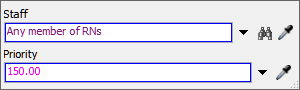
| Wait Area Return | This shared asset will link to the WaitingAreas location group. |
| Exam RN | This shared asset will link to the RNs staff group. |
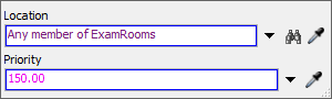
| Exam Room | This shared asset will link to the ExamRooms location group. |
| Acquire Exam Room (on the left) | This activity will attempt to acquire one of the Exam Room locations. If patients are currently using all of the Exam Room locations, the token will move to the Acquire Wait Area Return activity and the patient will find a chair in the waiting room. If one of the Exam Room locations is acquired, the token will move to the Escort Patient to Exam Room activity instead. |
| Acquire Wait Area Return | This activity will attempt to acquire one of the chairs in the WaitingArea1 multi-location. When the location is free, the patient token will move to the Escort Patient to Wait Area activity. |
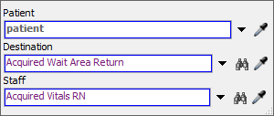
| Escort Patient to Wait Area | Once a chair in the WaitingArea1 multi-location has been acquired, this activity will tell the previously acquired Vitals RN to escort the patient back to the waiting area. |
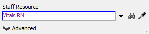
| Release Vitals RN (on the right) | This activity will release the Vitals RN that was acquired earlier in the process flow. Afterwards, the RN will then be free to work on other tasks or to be acquired by other patients. |
| Acquire Exam Room (on the right) | This activity will be identical to the Acquire Exam Room activity on the left except that it won't use a Max Wait Timer. |
| Release Wait Area Return | This activity will release the specific chair from the WaitingArea1 location so that it is free for other patients to acquire. |
| Acquire Exam RN | This activity will acquire a member of the RNs group. If all members of the RNs group are busy working on other tasks, the token will wait at this activity until an RN is free. |
| Escort Patient to Exam Room (on the right) | The Exam RN will then escort the patient to an exam room. |
| Release Exam RN | This activity will release the Exam RN that was acquired earlier in the process flow. Afterwards, the RN will then be free to work on other tasks or to be acquired by other patients. |
| Escort Patient to Exam Room (on the left) | This activity will be nearly identical to the Escort Patient to Exam Room on the right. However, the Vitals RN will escort the patient instead. |
| Release Vitals RN (on the left) | This activity will be identical to the Release Vitals RN activity on the right. |
To build this logic:
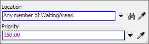
- In the Escort to Exam Room container shape, click the Wait Area Return shared asset to select it. In Quick Properties, click the arrow next to the Location box to open a menu. Point to Location Groups, then select WaitingAreas.
- Click the Exam RN shared asset to select it. In Quick Properties, click the arrow next to the Staff box to open a menu. Point to Staff Groups, then select ExamRNs.
- Click the Exam Room shared asset to select it. In Quick Properties, click the arrow next to the Location box to open a menu. Point to Location Groups, then select ExamRooms.
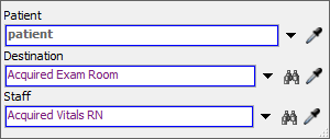
- Click the Escort Patient to Wait Area activity to
select it. In Quick Properties next to the Destination box,
click the Sampler button
to enter sampling mode.
- Click the Wait Area Return shared asset to sample it.
- In Quick Properties next to the Staff box, click the
click the Sampler button
to enter sampling mode.
- Click the Vitals RN shared asset in the Check Vitals shape to sample it.
- Click the Release Vitals RN activity in the right
activity block to select it. In Quick Properties next to the
Staff Resource box, click the Sampler
button to enter sampling mode.
- Click the Vitals RN shared asset in the Check Vitals shape to sample it.
- Repeat the previous steps for the Release Vitals RN activity in the activity block on the left.
- Click the Escort Patient to Exam Room in the activity
block on the left to select it. In Quick Properties next to the
Staff box, click the Sampler
button to enter sampling mode.
- Click the Vitals RN shared asset in the Vitals shape to sample it.
Reset and run the model:
After finishing the check vitals process, the nurse escort the patients to an exam room. At this stage in the model-building process, only two patients are arriving at the clinic, so there will always be an exam room open for them. Otherwise, they would get escorted to the waiting area. You could increase the number of patients arriving at the start of the model if you'd like to test this functionality.
Conclusion
Up to this point, you've created a simulation model of a health care clinic in which a patient completes the registration and check in process, then goes to an exam room. In the next tutorial task, you'll learn how to make a custom location object. Continue on to Tutorial Task 1.4 - Add a Custom Location Object.