Fluid Conveyor
Overview and Key Concepts
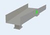
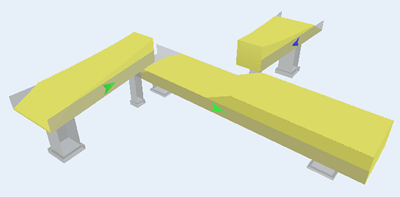
The Fluid Conveyor is used to control fluid flow through the use of multiple input and output ports. Inputs and outputs may be placed anywhere along the length of the conveyor. The direction, speed, acceleration and angle of repose along with the length and width of the conveyor are all factors that will affect where material rests inside the conveyor and when and to which output port the material will be sent.
Speed and Direction
The Fluid Conveyor cannot have a negative speed. If the target direction is changed, the Fluid Conveyor will decelerate to 0 speed and then accelerate to the target speed.
Slices
In order to simulate a moving fluid material, the Fluid Conveyor breaks all of its content up into a series of slices defined by the user. The more slices in the conveyor, the higher the resolution. This also means there is more processing required to move and repose the material through all the slices.
Inputs
Inputs are defined over a range of slices. For every tick where material moved into the Fluid Conveyor from one of the input ports, the incoming material will be spread evenly through all of the slices that fall inside the input range.
Outputs
Outputs are defined at one point along the conveyor. Each output has a forward and reverse output percentape as well as a stopped rate. The forward and reverse percentages specify the total percentage of material that should exit through that output based on the current direction. If the output cannot handle all of the material, it is either spilled onto the floor (see Allow Spillage) or it will pass the output. The stopped rate will cause material to flow through the output when the conveyor is stopped. For example, if the stopped rate is 0.1 and the material sitting on top of an output is 0.5, the output will take 0.1 fluid units per tick, until there is no more fluid available to take.
Angle of Repose
The angle of repose defines the material's steepest angle of descent of the slope relative to the horizontal plane. This angle ranges between 0 and 90 degrees. For example, dirt has an angle of repose of 30-45°, dry sand 34°, wet sand 15-30°, and water is 0°. The fluid conveyor also has a repose rate. A value of 0 will cause the Angle of Repose to be ignored.
Repose Rate
The repose rate defines how quickly a reposing pile of material will reach its natural resting state (based on the angle of repose). The repose subroutine will be run the number of times specified in this field (the larger the number, the more processing time it will take each tick to repose). A value between 1 and 10 is usually sufficient.
Allow Spillage
If allow spillage is checked on the Inputs/Outputs page, the fluid conveyor will try to send the full percentage of material to each output. Any material that cannot be handled by the downstream object will be spilled onto the floor. Any material that is unable to leave the conveyor through on output port that reaches the end of the fluid conveyor will also spill onto the floor. The spillage amount is recorded an a total amount of material spilled.
Sensors
Similar to the Fluid Tank's Marks, sensors can be added anywhere along the length of the Fluid Conveyor. These sensors can be set up to be triggered based on the Peak Height of a section, or on the total Volume of the section. Each sensor has a Start and an End position. This marks the range over which the sensor will look for the specific values. You can also specify the low, mid, and high values for each sensor. When fluid passes one of these values, a Sensor Trigger is fired.
States
For statistical purposes, the fluid conveyor will be in one of the following states at various points during a simulation run:
Idle
The Fluid Conveyor is stopped and there is no material in it.
Empty
The Fluid Conveyor is conveying but has no material in it.
Not Empty
The Fluid Conveyor is stopped and no material is entering or leaving.
Conveying
The Fluid Conveyor has material that is currently being moved along the length of the trough at a speed > 0.
Flowing
The Fluid Conveyor has material but it is stopped. Material is settling and flowing through outputs.
Releasing
The Fluid Conveyor is sending material downstream and no material is entering.
Collecting
The Fluid Conveyor is collecting material and no material is leaving.
Properties
The fluid conveyor object has seven tabs with various properties. The last four tabs are the standard tabs that are common to most fluid objects. For more information about the properties on those tabs, see:
The Statistics tab is obsolete and is not supported for this object any more. Use the Statistics group in the object's Quick Properties instead.
The remaining three tabs--the Conveyor tab, the Inputs/Outputs tab, and the Sensors tab are unique to the fluid conveyor object. The properties on these tabs will be explained in more detail in the next three sections.
The Conveyor Tab
The Conveyor tab has the following properties:
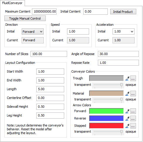
Maximum Content
The maximum amount of fluid material that this object can hold at any time.
Initial Content
The amount of material that is in the object when the model is reset.
Initial Product
This opens the Initial Product Window which allows the modeler to define the Product ID and sub-component mix of the material that is in this object.
Toggle Manual Control
Toggles manual speed control. You can change the direction, target speed and acceleration while the model is running. The manual speed control is designed to help you understand more about how the conveyor will react to changes in speed or direction.
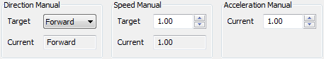
Direction
Specifies the initial direction of the conveyor. The current direction is also displayed while the model is running.
Speed
Specifies the initial speed of the conveyor in the given initial direction. Speed values for the fluid conveyor cannot be negative. The current speed is also displayed while the model is running.
Acceleration
Specifies the initial acceleration of the conveyor. Infinite acceleration is defined as 0. The current acceleration is also displayed while the model is running.
Number of Slices
The number of slices of fluid material that are placed along the length of the conveyor. The more slices, the better the resolution for displaying the volume of fluid. However, the more slices in the fluid conveyor, the more computations, causing your model to run slower.
Angle of Repose
Defines the material's steepest angle of descent of the slope relative to the horizontal plane. This angle ranges between 0 and 90 degrees.
Repose Rate
The repose rate defines how quickly a reposing pile of material will reach its natural resting state (based on the angle of repose). A value of 0 will cause the Angle of Repose to be ignored. The repose subroutine will be run the number of times specified in this field (the larger the number, the more processing time it well take each tick to repose).
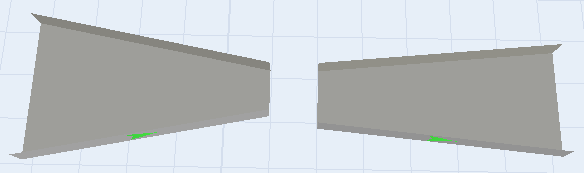
Layout Configuration
The layout of the fluid conveyor affects the conveyor's behavior, so the model should be reset after the layout has been changed to apply the changes.
Start Width
Specifies the width of the start of the conveyor.
End Width
Specifies the width of the end of the conveyor.
Length
Specifies the length, or X dimension of the conveyor.
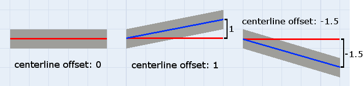
Centerline Offset
The centerline offset skews the conveyor's trough. The value specifies the distance and direction (can be positive or negative) that the centerline of the trough is offset from the standard centerline.
Sidewall Height
Specifies the sidewall height of the conveyor's trough. This value is purely visual and has no effect on the behavior of the fluid conveyor.
Leg Height
Specifies the leg height of the conveyor. This value is purely visual and has no effect on the behavior of the fluid conveyor.
Conveyor Colors
Use the or to Sample a color or press
"..." to choose a color.
or to Sample a color or press
"..." to choose a color.
Trough
Sets the color of the trough and legs. You may also change the transparency of the trough (allowing you to see the material's height profile through the sidewall).
Material
Sets the color of the material. You may also change the transparency.
Arrow Colors
Set the color of the three directions of the fluid conveyor, Forward, Reverse, and Stopped. You may also change the transparency.
The Inputs/Outputs Tab
The Inputs/Outputs tab has the following properties:
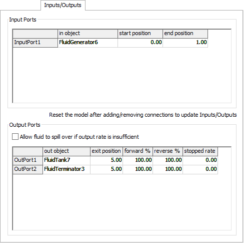
Input Ports Table
Displays all of the objects currently connected to an input port of the Fluid Conveyor:
- In Object - Displays the name of the input object.
- Start Position - The start point of the input. This value is in the model's length units and must be greater than or equal to 0 and less than the end position.
- End Position - The end point of the input. This value is in the model's length units and must be less than or equal to the length of the Fluid Conveyor and greater than the start position.
- Allow Spillage - If this is checked, fluid will be allowed to spill at outputs if the downstream object cannot take as much fluid as the Fluid Conveyor is sending. Any extra fluid left at the end of the conveyor will also spill. Total spillage is tracked each tick.
Output Ports Table
Displays all of the objects currently connected to an output port of the Fluid Conveyor:
- Out Object - Displays the name of the output object.
- Exit Position - The exit point of the output. This value is in the model's length units and must be greater than or equal to 0 and less than the end position.
- Forward % - This specifies the percentage of fluid that should exit at this output when the Fluid Conveyor is moving forward. The Fluid Conveyor will attempt to send the specified percentage of fluid through the output. If the downstream object cannot handle the total amount of fluid, it will pass the output, unless spillage is allowed, then the excess will spill onto the floor.
- Reverse % - This specifies the percentage of fluid that should exit at this output when the Fluid Conveyor is moving forward. The Fluid Conveyor will attempt to send the specified percentage of fluid through the output. If the downstream object cannot handle the total amount of fluid, it will pass the output, unless spillage is allowed, then the excess will spill onto the floor.
- Stopped Rate - The stopped rate specifies how much fluid should leave through the output when the Fluid Conveyor is stopped. For example, if the stopped rate is 0.1 and the material sitting on top of an output is 0.5, the output will take 0.1 fluid units per tick, until there is no more fluid available to take.
The Sensors Tab
The Sensors tab has the following properties:
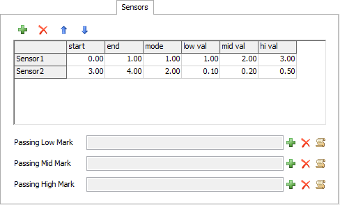
Sensor Table
Displays all of the sensors for the Fluid Conveyor:
| Icon | Description |
|---|---|
 |
Adds a new sensor to the table. |
 |
Removes the selected sensor from the table, or if no sensor is selected, removes the last sensor in the table. |


|
Moves the selected sensor up or down in the list. |
This table has the following columns:
- Start - The starting point of the sensor. This value is in the model's length units and must be greater than or equal to 0 and less than the end point.
- End - The end point of the sensor. This value is in the model's length units and must be less than or equal to the total length of the conveyor and greater than the start point.
- Mode - The sensor has two modes, Volume(1) and Peak Height(2). Volume will look at the total volume between the starting and ending point. Peak Height will look at the highest point between the starting and ending point.
- Low, Mid, High Val - These values specify the low, mid, and high points for the volume or peak height that, when crossed, will trip the sensor. When the volume or peak height of material in a sensor range rises or falls through any of these three values, one of the three passing triggers will fire.
Sensor Triggers
The sensors have the following triggers:
- Passing Low Mark - This trigger is fired when fluid volume or peak height rises or palls through the defined Low Val.
- Passing Mid Mark - This trigger is fired when fluid volume or peak height rises or palls through the defined Mid Val.
- Passing High Mark - This trigger is fired when fluid volume or peak height rises or palls through the defined High Val.