Network Node
Overview and Key Concepts
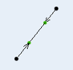
Network nodes are used to define a network of paths that transporters and operators follow. The paths can be modified using spline points to add curvature to the path. By default, objects travelling on a network will follow the shortest path between their origin and destination.
Events
For information on events, see the Event Listening page.
The network node has the following events:
On Arrival
On Arrival fires when a traveler arrives at the node.
It has the following parameters:
| Event Parameter | Type | Explanation |
|---|---|---|
| Traveler | Object | The object traversing the network |
| To Edge | int | The rank of the edge the traveler will continue on |
| From Edge | int | The rank of the edge the traveler arrived on |
On Continue
On Continue fires right before a traveler leaves the node.
It has the following parameters:
| Event Parameter | Type | Explanation |
|---|---|---|
| Traveler | Object | The object traversing the network |
| To Edge | int | The rank of the edge the traveler will continue on |
| From Edge | int | The rank of the edge the traveler arrived on |
States
The network node does not implement any states.
Statistics
The network node does not track any statistics.
Properties
The network node object has four tabs with various properties. The last three tabs are common to Travel Network objects. For more information about the properties on those tabs, see:
Only the NetworkNode tab is unique to the network node object. The properties on this tab will be explained in more detail in the following sections.
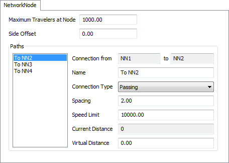
Maximum Travelers at Node
This number defines how many transporters that are not traveling on the network can be stationed at the node. This would represent the transporters that are not currently executing a travel task, but are doing other things while "stationed" at the node.
Side Offset
This number defines a distance to the right of outgoing paths that travelers will be offset. It does not affect the distance that the traveler travels, but is purely for visual purposes, so travelers going in different directions along the same path don't run over each other.
Name
This field allows the user to name each connection in the network. These names should be descriptive of any special purpose this connection has in the model.
Connection Type
This drop-down list allows the user to define how this connection behaves. There are three options.
No Connection
Transporters cannot travel on this connection. The connection is drawn in red in the view window.
Passing
Transporters are allowed to pass each other on this connection. The connection is drawn in green in the view window.
No Passing
Transporters will not pass each other on this connection. The minimum distance between transporters on the path can be set by the user in the Spacing field of the dialog. These connections are drawn in yellow in the view window.
Spacing
This number determines the minimum distance allowed between two transporters on a connection that is designated as no passing. This is the distance from the back of one traveler to the front of the traveler behind it.
Speed Limit
This number determines the maximum speed that a traveler can travel along this connection.
Current Distance
This number shows you the current distance that is being simulated for that connection. If the virtual distance is specified as 0, then it will be the actual distance of the spline path. Otherwise it will be the distance that is specified in the virtual distance field.
Virtual Distance
This number let's you specify an exact distance for the connection.