View Settings
Types of Views
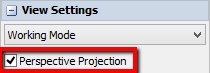
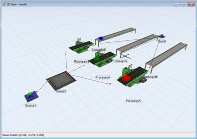
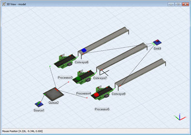
The 3D view may be toggled between orthographic and perspective modes by deselecting all objects in the 3D view and checking/unchecking the Perspective Projection option in the Quick Properties window.
Perspective projection gives the model a more 3D world feel.
Where as the orthographic view has no depth.
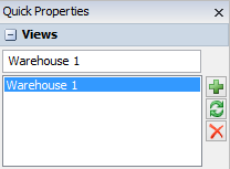
The Views Group
The Views utility is found in the Quick Properties window when there are no objects selected in the 3D view. It allows you to capture the view's current camera position and add it to a list of views.
It has the following properties:
View Name
Rename the selected view by typing a new name in this field.
View List
Select a view from the list to rotate/move to that view.
Buttons
| Button | Explanation |
|---|---|
 |
Captures the current view |
 |
Updates the currently selected view to the camera's current position/rotation |
 |
Removes the selected view from the list |
The View Settings Group
These settings are directly underneath the Views group in Quick Properties.
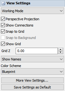
Mode
This option gives you two view setting presets. Switching to Presentation mode turns of Connections, the Grid, and Object Names.
Perspective Projection
This option toggles the 3D view from being a Perspective View, to displaying as an Orthographic View. The Perspective View looks more real-world where as the Orthographic view has no depth.
Show Connections
If this box is checked, objects will draw their connections to other objects.
Snap to Grid
If this box is checked, objects will automatically move to the nearest grid line when they are moved in the model. This is useful for placing objects in precise locations. Resizing of objects will also snap to the grid if this is checked.
Snap to Background
If this box is checked, objects will automatically move to the nearest background snap point of the first model background object when they are moved or resized in the model.
Show Grid
If this box is checked, the grid will be drawn in the view window.
Grid Z
Changes the z position of the grid to more easily create multi-floor models. Objects added to the model will be placed at this z position.
Color Scheme
These presets modify the 3D view colors.
More View Settings...
Opens a pane in the left pane with additional view settings. These settings are discussed in the More View Settings section.
Save Settings as Default
As described above, 3D View Settings are not saved and will be lost when the 3D view is closed. This will save your current View Settings as default for any new 3D views that are opened.
More View Settings
The More View Settings opens in the left pane and give additional settings.
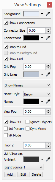
Background Color
This option lets you select the color of the view window's background from a standard Windows color-choosing dialog box.
Show Connections
If this box is checked, the ports and port connection lines will be displayed in the view window. Hiding these connections often makes it easier to see what is happening in the model. If a model is slowing down, often un-checking this box will help speed it up.
Connector Size
This number sets how large the port connectors are on the object.
Connections Color
This value sets the color of the connector lines in the view.
Snap to Grid
If this box is checked, objects will automatically move to the nearest grid line when they are moved in the model. This is useful for placing objects in precise locations. Resizing of objects will also snap to the grid if this is checked.
Snap to Background
If this box is checked, objects will automatically move to the nearest background snap point when they are moved or resized in the model.
Show Grid
If this box is checked, the grid will be drawn in the view window.
Grid Fog
This value lets you have the view's grid fade into the background color as it gets further from the viewpoint. Usually this is only useful on a perspective view. Set the value between 0 and 1, 0 meaning no fade, 1 meaning full fade.
Grid Line Color
This value sets the color of the grid lines.
Show Names
This pull-down list allows you to choose whether names and stats are shown or hidden in the 3D view.
Name Style
This pull-down list allows you to choose where the name of the object will be drawn. Choose either below the object or above the object.
Names Color
This value sets the color of object names displayed in the 3D view.
View Fog
This value sets the view's fog value. View fog causes objects that are far away from the camera position to fade into the background color. Set the value between 0 and 1, 0 meaning no fog, and 1 meaning complete fog. This is usually only applicable to a perspective window.
Show 3D Shapes
If this box is checked, the 3D shapes (.3ds files or .wrl files) for all the objects in the model will be drawn in the view window. Some objects do not have 3D files associated with them, they are generally drawn directly with OpenGL. These objects will not be affected by this box.
1st Person
If this box is checked, the view window's mouse controls will be in first person mode. This means that the view will rotate around the user's view point, and not around a point in the middle of the screen. This mode is most useful when navigating in fly-through mode.
Ignore Objects
If this box is checked, the user will not be able to click on any objects in the view window. This is useful for navigating around a model that is completed, as the user will not be able to accidentally move any objects.
Sync Views
If this box is checked, all open view windows will be updated at the same time. If it is not checked, some windows may not be updated until an action is completed in a different window. Checking this box may cause the program to run a little slower.
VR Mode
Checking this box will cause the view to be rendered on a connected virtual reality headset. FlexSim works with Oculus Rift and HTC Vive VR headsets. The view will also render and handle inputs from VR motion controllers (Oculus Touch or HTC Vive controllers) if this box is checked. If you are using an Oculus Rift, ensure that Unknown Sources is checked in your Oculus Settings.
RTX Mode (Beta)
Checking this box will cause the view to be rendered using Nvidia's OptiX ray tracing engine. This rendering mode is only available using 64-bit FlexSim on compatible Nvidia graphics cards and drivers.
Nvidia RTX graphics cards (Turing architecture) have RT cores that improve the performance of RTX Mode. Some older Nvidia graphics cards (such as Maxwell, Pascal, and Volta architectures) can work with RTX Mode with lower performance.
RTX Benefits
- Improved shadows. All of the scene's light sources (including point source lights) can cast shadows, and the resolution of the shadows is not determined by rendering the scene multiple times into cascading shadow map textures.
- Unlimited light sources. RTX Mode can use any number of light sources, although performance will decrease as the number of lights increases.
- Order-independent transparency. Transparent meshes do not have to be drawn after other meshes when using RTX Mode, and the order of the triangles within a translucent mesh does not affect how it is rendered.
RTX Limitations
- Only triangles. RTX Mode currently only renders meshes drawn with GL_TRIANGLES. Other draw modes, such as lines and points, are not supported.
- Slow bone animations. In RTX Mode, bone animations are currently being calculated on the CPU rather than in a vertex shader on the GPU. This causes models with bone animations to run slower in RTX Mode than with the default shader rendering.
RTX Future Improvements
- RTX Mode is currently using a shading technique that resembles FlexSim's default shaders. Future improvements could include more realistic soft shadows, physically based materials, reflections, refraction, ambient occlusion, global illumination, and other ray tracing techniques.
Ambient Color
This value sets the color of light that is applied to all faces equally regardless of location.
Light Sources
The pull-down list contains all of the light sources that are currently in the view window.
Edit
This button opens the Light Source Editor for the light currently showing the pull-down list.
Add
This button will create a new light source in the view window.
Delete
This button will delete from the view window the light source currently showing in the pull-down list. There must always be at least one light source in the model.
Light Source Editor
This dialog can be accessed by opening the View Settings and clicking the Edit button in the Light Sources group.
This tool has the following properties:
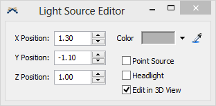
X Position
This number is the position along the X axis of the model where this light source is located.
Y Position
This number is the position along the Y axis of the model where this light source is located.
Z Position
This number is the position along the Z axis of the model where this light source is located.
Color
This allows the user to choose the color of the light from this light source.
As point source
If this box is checked, the light generated by this light source appears to be coming from a specific point, relative to the camera. If it is not checked, the light appears to be coming from a given direction only.
Headlight
If this box is checked, the light light source will move with the camera acting as a headlight.
Edit in 3D View
If this box is checked, a lightbulb object will be displayed in the 3D view and allow you to move the light source to a desired position.