Task 1.2 - Tasks Using Resources
Task Overview
In this tutorial task, you'll get a comprehensive introduction to building tasks using resources in a process flow. This tutorial will show you some of the advantages and disadvantages of working with resources, such as:
- Adding intermediate tasks
- Adding additional task executers
- Combining process flow logic with standard logic
You'll build a series of different simulation models, finally ending in one that works similar to the following image:
Step 1 Copy and Modify the 3D Model
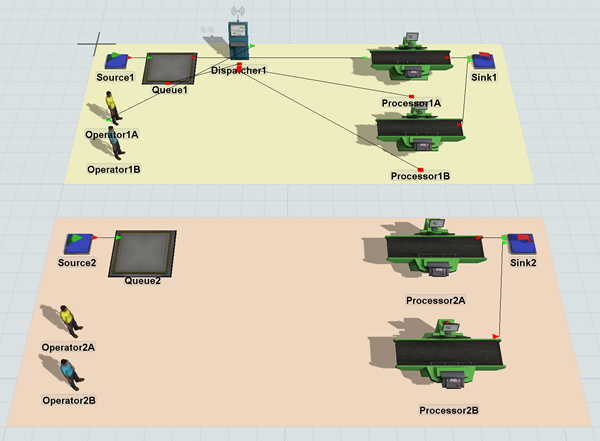
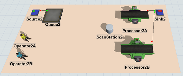
In this step, you'll copy the original system you used to build the standard logic. In the next step, you'll change this system so that it uses process flow logic instead. When you're finished, your 3D model should look similar to the following image:
To copy the plane:
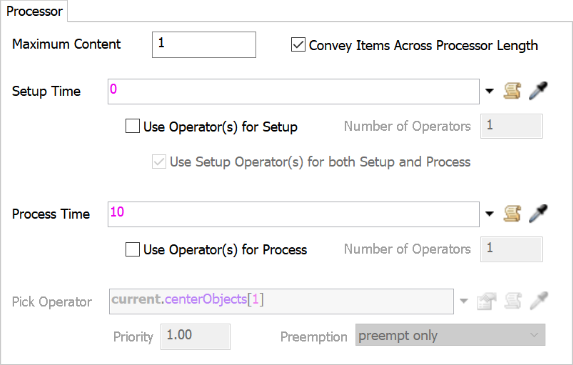
- Double-click Processor1A to open its properties window.
- On the Processor tab, change the
Setup Time to
0. - Clear the Use Operator(s) for Setup checkbox.
- Click the OK button to save the changes and close the window.
- Click the StandardLogic plane to select it.
- Press Ctrl+C to copy the plane and all the objects on it. Click somewhere blank in the model to de-select the original plane. Then, press Ctrl+V to copy the plane.
- With the copied plane selected, change the name of the plane to ResourceLogic in Quick Properties.
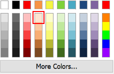
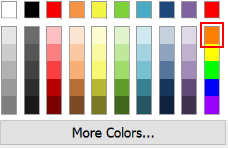
- Click the arrow next to the color box to open the color selector menu. Choose the lightest shade of orange.
- Delete Dispatcher1 from the newly copied plane.
- Rename each of the 3D objects on the copied plane replacing any 1 numbers with a 2, such as Sink2, Operator2A, Processor2A, etc.
- Remove the following port connections (press and hold the Q key while clicking
two connected objects):
- From Queue1 to Processor1B (in the StandardLogic plane)
- From Queue2 to Processsor2A (in the ResourceLogic plane)
- From Queue2 to Processor2B (in the ResourceLogic plane)
Check to ensure that your 3D model looks similar to the image shown at the beginning of this step.
Step 2 Create Tasks Using Resources
In this step, you'll add activities to a general process flow to build a process flow that uses resources to create transportation task logic.
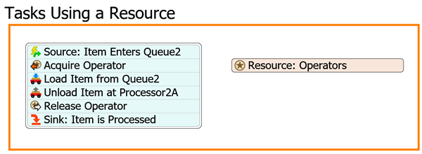
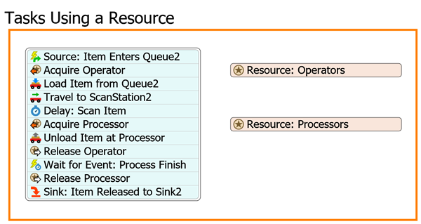
When you're finished, your process flow should look similar to the following image:
For now, you'll merely add and connect these activities to the process flow. You'll edit the properties to add the functionality in a later step.
To add and connect these activities:
- On the main toolbar, click the Process Flow button to open a menu. Select Add a General Process Flow.
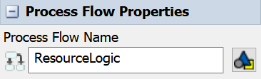
- Click a blank space in the process flow so that nothing is selected. In Quick Properties, change the name of the process flow to ResourceLogic.
- With the process flow open and active, add a Process shape (under Flowchart) from the Library, dragging it into the process flow.
- In Quick Properties, change the name of the shape to Tasks Using a Resource.
- Click the arrow next to the Color box to change it to orange. You'll use orange because it matches the color of the ResourceLogic plane.
- In the Tasks Using a Resource shape, add the following
activities to create a stacked block:
- An Event-Triggered Source (under Token Creation)
- An Acquire Resource (under Shared Assets)
- A Load (under Task Sequences)
- An Unload (under Task Sequences)
- A Release (under Shared Assets)
- A Sink (under Basic)
- Add a Resource shared asset (under Shared Assets) next to the stacked block.
- Rename the activities as follows:
| Activity | New Name |
|---|---|
| Source | Source: Item Enters Queue2 |
| Acquire | Acquire Operator |
| Load | Load Item from Queue2 |
| Unload | Unload Item at Processor2A |
| Release | Release Operator |
| Sink | Sink: Item is Processed |
| Resource | Resource: Operators |
Check to make sure your process flow looks similar to the image shown in the beginning of this step.
Step 3 Create the Process Flow Logic
In this step, you'll edit the properties for the activities in the process flow. The following is an overview of how each activity and shared asset will function:
| Activity | Explanation |
|---|---|
| Resource: Operators | You'll link this shared activity to Operator2A in the 3D model so that it can be acquired for the transportation tasks. |
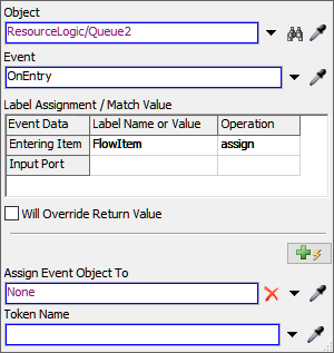
| Source: Item Enters Queue2 | The Event-Triggered Source is an event-listening activity that will listen to events in the 3D model. When a flow item enters the Queue2, this activity will create a token and release it to the next downstream activity. You'll assign a label to this token named FlowItem that will contain a reference to the specific flow item that triggered the event. |
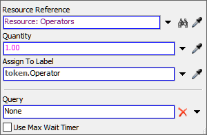
| Acquire Operator | This activity will attempt to acquire a resource (Operator2A) to work on the transportation tasks. If the operator is not available to work on the task, the token will wait at this activity until the operator becomes available. If the operator is available to work on the task, the token will acquire that resource and release the token to the next downstream object. When the resource is acquired, you'll assign the token a label named Operator that will contain a reference to Operator2A. |
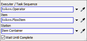
| Load Item at Queue2 | This activity tells the operator which flow item needs to be picked up and where it is located. It will use the Operator label to assign the task to the same operator that was acquired previously and it will use the FlowItem label to tell the operator which item should be transported. |
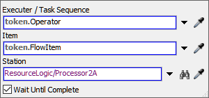
| Unload Item at Processor2A | This activity tells the operator where to unload the flow item. It will use the Operator label to assign the task to the same operator that was acquired previously and it will use the FlowItem label to tell the operator which item should be transported. For now, you'll sample Processor2A to tell the operator where to unload the flow item. |
| Release Operator | When the transportation task is complete, this activity will release the operator. It will use the Operator label to release the operator. |
| Sink: Item is Processed | This activity removes the token from the process flow. You'll use its default settings. |
To create this functionality:
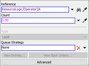
- Click the Resource: Operators shared asset to select
it. In Quick Properties, next to the Reference box, click
the Sampler button
 to enter sampling mode.
 - In the 3D model, click Operator2A to sample it.
- Click the Source: Item Enters Queue2 activity to select
it. Click the Exclamation Point button
 next to this activity to enter
sampling mode.
next to this activity to enter
sampling mode. - In the 3D model, click Queue2 to open a menu. Select Queue2: On Entry. The name of the sampled object will appear next to the activity.
- In Quick Properties, in the Label Assignment table, click the cell that is on the Entering Item row under the Label Name or Value column. Type FlowItem.
- Click the cell on the Entering Item row under the Operation to open a menu. Select assign.
- Click the Acquire Operator activity to select it. Click
the Exclamation Point button
next to this activity to enter
sampling mode.
- Click the Resource: Operators shared asset to sample it. A blue line will now link this activity to the shared asset.
- In Quick Properties, in the Assign to Label box, delete
the current text and type
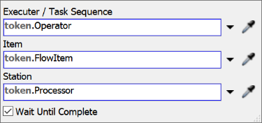
token.Operator. - Click the Load Item from Queue2 activity to select it. In Quick Properties, click the arrow next to the Executer / Task Sequence box to open a menu. Point to Token Label and select Operator.
- Click the arrow next to the Item box to open a menu. Point to Token Label and select FlowItem.
- Click the Unload Item at Processor2A activity to select it. In Quick Properties, click the arrow next to the Executer / Task Sequence box to open a menu. Point to Token Label and select Operator.
- Click the arrow next to the Item box to open a menu. Point to Token Label and select FlowItem.
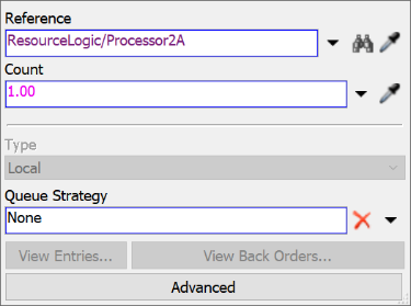
- Next to the Station box, click the
Sampler button
to enter sampling mode.
- In the 3D model, click Processor2A to open a menu. Select ResourceLogic/Processor2A.
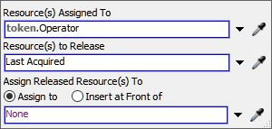
- Click the Release Operator activity to select it. Click the arrow next to the Resource(s) Assigned To box to open a menu. Point to Token Label and select Operator.
Reset and run the model:
Similar to the way the operator works with the standard 3D object logic, the operator using the process flow will transport arriving flow items to the processor. You'll also notice that tokens in the process flow represent the flow items as they move through the transportation tasks.
However, notice that the operator using the resource logic is slightly more efficient than the operator using the standard logic. Operator2A travels back to the queue to load another flow item rather than waiting at Processor2A until it has finished processing the item and opened its ports. You'll want to be mindful of these kinds of differences since they can affect the statistical data you'll get from the model.
Step 4 Add Additional Operators
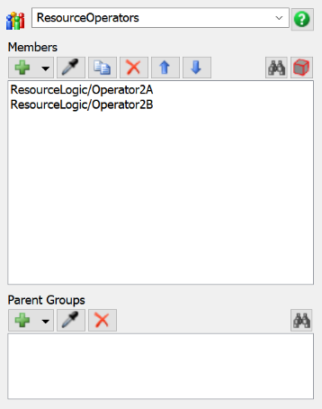
In this step, you'll learn how to add a second operator to help with the transportation tasks. You'll do this by adding Operator2A and Operator2B to a new object group called ResourceOperators. Then, you'll link the ResourceOperators group to the Resource: Operators shared asset.
The process flow's logic won't need to change much because the Operator label on the tokens can adapt easily to using two operators. This label will simply contain a reference either Operator2A or Operator2B, depending on which operator is acquired. This label will then be used to assign all the subsequent tasks and activities to that operator.
You'll also re-add the second operator to the standard logic model for comparison at the end of this step.
To make these changes:
- In the 3D model, right-click Operator2A to open a menu. Point to Object Groups and select Add to New Group.
- In the group properties window, change the name of the group to ResourceOperators.
- Click the Sampler button
to enter sampling mode.
- In the 3D model, click Operator2B to sample it and add it to the group.
- Close the group properties window.
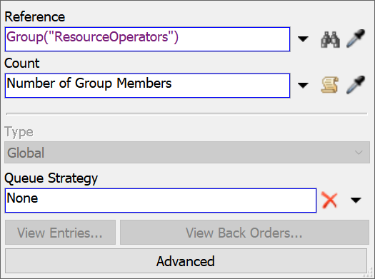
- In the ResourceLogic process flow, click the Resource: Operators shared asset. In Quick Properties, click the arrow next to the Reference box to open a menu. Point to Group, then select ResourceOperators.
- In the 3D model, create a port connection (A-connect) from Dispatcher1 to Operator1B.
Reset and run the model:
You can now compare the two sets of operators as they work on transportation tasks in the two models. Notice that the operators using the resource process flow are somewhat more efficient than the operators using the standard logic.
In fact, they might actually be too efficient: they're loading too many items onto the processor at a time. These differences might seem subtle, but they can eventually impact the quality of the statistical information you collect from your simulation model. You'll learn how to fix this problem in the next step.
Step 5 Add a Resource for the Processor
Notice that the simulation model controlled by the resource process flow now has another potential problem: both operators unload their flow items onto the processor one right after another so that the processor is sometimes processing two items at once. Contrast that with the standard logic system in which there can never be more than one flow item in the processor by default.
Keep in mind that this is only a potential problem, depending on whether you wanted to limit how many flow items could be processed at a time. If you wanted to better emulate the standard logic and restrict how many items can be loaded onto the processor, you can fix this problem with several possible solutions in a process flow. This step will demonstrate how to solve this problem using resources. You'll create a resource to represent the availability of the processor in the model.
You'll add some additional activities to the process flow to control the processor. When you're finished, your process flow will look similar to the following image:
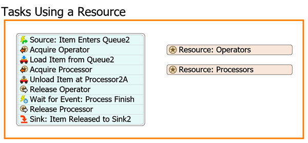
The following is an overview of how the new activities and shared assets will function:
| Activity | Explanation |
|---|---|
| Resource: Processors | You'll link this resource to Processor2A in the 3D model so that it can be acquired as a destination for the flow items. |
| Acquire Processor | This activity will attempt to acquire a processor when an operator is ready to unload a flow item. If the processor is not available to receive the flow item, the token will wait at this activity until the processor becomes available. If the processor is available, the token will acquire that resource and release the token to the next downstream object. When the resource is acquired, you'll assign the token a label named Processor that will contain a reference to Processor2A. |
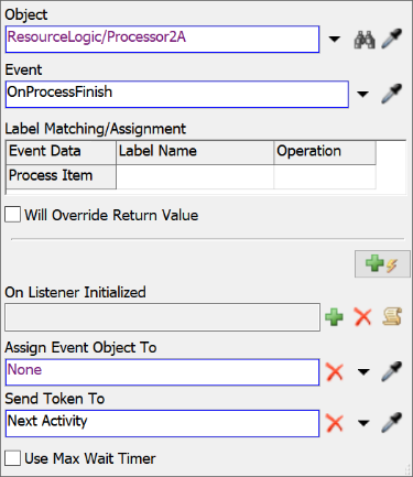
| Wait for Event: Process Finish | This is an event-listening activity, which means it will listen to an object in the 3D model and release the token to the next downstream activity once the event occurs. This activity will wait for the processor to finish processing the item before releasing the token to the next activity. |
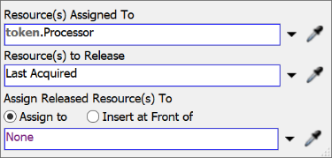
| Release Processor | This activity will release the processor so that it can accept another flow item. It will use the Processor label to release the processor. |
To make these changes:
- With the process flow active, drag a Resource and place it somewhere under the Resource: Operators in the process flow.
- Drag an Acquire Resource activity (under Shared Assets) and insert it after the Load Item from Queue2 activity.
- Drag a Wait for Event activity (under Basic) and insert it after the Release Operator activity.
- Drag a Release Resource activity (under Shared Assets) and insert it after the Wait for Event activity.
- Rename the new activities and shared asset (and one additional activity):
- Click the Resource: Processor shared asset to select
it. In Quick Properties next to the Reference box, click
the Sampler button
to enter sampling mode.
- In the 3D model, click Processor2A to sample it.
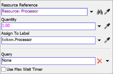
- Click the Acquire Processor activity to select it.
Click the Exclamation Point button
next to the activity to enter
sampling mode.
- Click the Resource: Processor shared asset to sample it. A blue line will now link this activity to the shared asset.
- In Quick Properties, in the Assign to Label box, delete
the current text and type
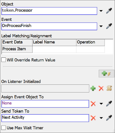
token.Processor. - Click the Wait for Event: On Process Finish activity to
select it. Click the Exclamation Point button
next to the activity to enter
sampling mode.
- In the 3D model, click Processor2A to open a menu. Select Processor2A: On Process Finish.
- Click the Release Processor activity to select it. Click the arrow next to the Resource(s) Assigned To to open a menu. Point to Token Label, then select Processor.
| Activity | New Name |
|---|---|
| Resource | Resource: Processors |
| Acquire | Acquire Processor |
| Wait for Event | Wait for Event: Process Finish |
| Release | Release Processor |
| Sink: Item Is Processed | Sink: Item Released to Sink2 |
Reset and run your model:
Notice that now the operators will wait until the processor is free before loading a flow item. Notice also that the logic is now very similar to what happens in the standard logic model. The only difference is where the operators stand when waiting for their next task. Unfortunately, that also reduces the overall efficiency of the operators in the resource process flow model, making the second operator unnecessary.
Step 6 Add Additional Processors
In this step, you'll add a second processor to increase the system's efficiency. You'll need to update some of the process flow's logic so that it uses the Processor label rather than a direct reference to the processors in the 3D model. Using the Processor label allows the process flow logic to adapt to more than one processor easily. This label will simply contain a reference to either Processor2A or Processor2B, depending on which processor is acquired. Various activities in the process flow will use this label to control the logic of the 3D model.
At the end of this step, you'll also re-add the second processor to the standard logic model for comparison.
To make these changes:
- In the 3D model, right-click Processor2A to open a menu. Point to Object Groups and select Add to New Group.
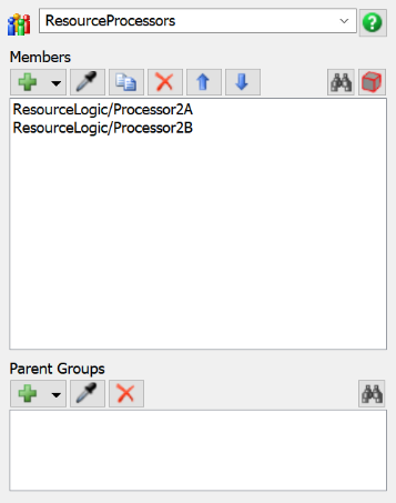
- In the group properties window, change the name of the group to ResourceProcessors.
- Click the Sampler button
to enter sampling mode.
- In the 3D model, click Processor2B to sample it and add it to the group.
- Close the group properties window.
- In the ResourceLogic process flow, click the Resource: Operators shared asset. In Quick Properties, click the arrow next to the Reference box to open a menu. Point to Group, then select ResourceProcessors.
- Click the Unload Item at Processor2A activity to select it. Change the activity's name to Unload Item at Processor for clarity.
- In the Quick Properties for this activity, click the arrow next to the Station box to open a menu. Point to Token Label, then select Processor.
- Click the Wait for Event: Process Finish activity to select it. In Quick Properties, click the arrow next to the Object box to open a menu. Point to Token Label, then select Processor.
- In the 3D model, create a port connection (A-connect) from Queue1 to Processor1B.
Reset and run the model:
Notice that now the two models work mostly identically, with the resource process flow model operating at a slightly more efficient level. The resource process flow model operates more efficiently because the operators don't wait at the processor while items are being processed. They save time by walking back to the queue while the processor is still processing the flow item.
Step 7 Change the Order of Tasks
In the previous step, you saw how the resource process flow model was slightly more efficient than the model that used standard logic. For the sake of learning an important concept about FlexSim logic in general, you'll change the order of tasks in this process flow and observe how that change affects the behavior of operators in the 3D model.
To make this change:
- In the Tasks Using a Resource shape in the process flow, click the stacked block of activities to select it.
- Click the Unlink buttons
 before and after the
Load Item from Queue2 activity to separate it from the
stacked block.
before and after the
Load Item from Queue2 activity to separate it from the
stacked block. - Drag the Load Item from Queue2 activity so that it is after the Acquire Processor activity in the second stacked block.
- Drag the second stacked block and snap it to the end of the first stacked block.
Reset and run the model:
As you watch this simulation run, now the operators in the resource process flow model wait at the processor while the items are being processed, rather than traveling back to the queue. That's because the Acquire Processor activity must be complete before the Load Item from Queue2 activity can begin, so the operator won't begin traveling right away. (You could change this if you put a Travel activity before the Acquire Processor activity.) Notice that one simple change in the order of activities in your process flow completely changes the behavior of the operators.
You might have noticed that, even now, the two simulation models aren't entirely identical. The operators in the standard logic model now actually complete the tasks more efficiently than the operators in the resource process flow model. The differences are caused by subtle differences between the standard logic and the resource process flow. Behind the scenes, the standard 3D logic is explicitly adding Travel tasks in between the loading and unloading tasks, which changes the speed that the operators walk as they near their destination. If you were to add two travel tasks, in front of the Load and Unload activities, the two model would be identical again.
There's a few key take-aways you should remember from this step:
- The order in which you add activities in the process flow can create small, but important changes to the way the 3D model behaves.
- The timing of events also creates small but important changes to the model.
- Even though these differences might not seem significant, over time they will impact the statistical data you get from your model.
Step 8 Add a Custom Task
Up to this point, you've learned how to merely replicate standard logic using resources in a process flow. In this step, you'll begin to see how the process flow method has a major advantage over the standard logic: it can handle customization much better. You can easily create custom tasks that better represent the business system you're trying to model.
In this step, you'll customize the task sequence by adding an intermediate task. You'll add a shape (a kind of visual object) to the 3D model to represent the station where the operator will need to scan flow items before unloading them at the processor:
Then you'll add and rename two additional activities to the process flow that will simulate the scanning tasks. When you're finished, your process flow will look similar to the following image:
The following is an overview of how the two new activities will function:
| Activity | Explanation |
|---|---|
| Travel to ScanStation2 | This activity will tell the operator to travel to the ScanStation2 object. |
| Delay: Scan Item | This activity will simulate the amount of time that it takes to scan the flow item in the computer. You'll set the delay to 1 second. |
To make these changes to your simulation model:
- With the 3D model active, drag a Shape (under Visual) and place it near Processor2A and Processor2B.
- Double-click the Shape to open its properties window.
- In the name box at the top of the window, change the name of the shape to ScanStation2.
- On the General tab in the Flags group, check the Show Name box.
- Press OK to save the changes and close the window.
- In the Tasks Using a Resource shape in the process flow, click the stacked block of activities to select it.
- Click the Unlink buttons
before and after the
Load Item from Queue2 activity to separate it from the
stacked block.
- Drag the Load Item from Queue2 activity so that it is before the Acquire Processor activity in the first stacked block.
- Drag a Travel activity (under Task Sequences) from the Library and insert it after the Load Item from Queue2 activity.
- Drag a Delay activity (under Basic) and insert it after the Travel activity.
- Rename the two new activities:
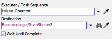
- Click the Travel to ScanStation2 activity to select it. In Quick Properties, click the arrow next to the Executer / Task Sequence box to open a menu. Point to Token Label and select Operator.
- Next to the Destination box, click the
Sampler button
to enter sampling mode.
- In the 3D model, click ScanStation2 to open a menu. Select ResourceLogic/ScanStation2.
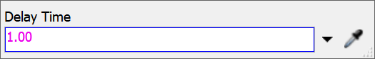
- Click the Delay activity to select it. In Quick
Properties in the Delay Time box, delete the current text
and type
1.00.
| Activity | New Name |
|---|---|
| Travel | Travel to ScanStation2 |
| Delay | Delay: Scan Item |
Reset and run the model:
As you watch, the operators will take the flow item to the scanner and delay briefly before loading it on the processors. Notice that it was relatively easy to insert a simple intermediate task into this process flow. Unfortunately, there is no easy way to create this in the standard logic without writing custom code in Flexscript.
Step 9 Use the Resource With Standard Logic
What happens if you use resource logic in combination with the standard 3D object logic? In this step, you'll explore what happens if you mix and match the two approaches to creating tasks. You'll use standard logic to assign Operator2A to help with Processor1B's process time and see how that affects the task logic.
To make these changes:
- In the 3D model, create a center port connection (S-connect) from Processor1B to Operator2A.
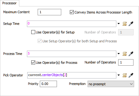
- Double-click Processor1B to open its properties window.
- On the Processor tab, check the Use Operator(s) for Process checkbox.
- In the Pick Operator box, type
current.centerObjects[2]. - Make sure the Priority box is set to
0.00.
Reset and run the model:
Notice that Operator2A keeps getting interrupted in the middle of transporting and scanning flow items to run Processor1B for 5 seconds. Operator2A often walks over to run Processor1B while still holding a flow item that it was in the middle of transporting or scanning.
These interruptions happen because Operator2A performs tasks using FIFO (first in first out) logic. In other words, the operator will do tasks in the order in which it receives the tasks that are assigned to it. It doesn't distinguish between tasks that were given to it by either the process flow or Processor1B. You probably don't want this kind of behavior, especially since you would expect that once a resource was acquired, it couldn't work on any other tasks until the transportation tasks were finished.
This interruption problem is one of the weaknesses of using the resource shared asset to build tasks. The resource doesn't work well with the standard 3D object logic if you would like to combine elements of both.
Conclusion
Now that you've built transportation tasks using resources in a process flow, you can see that it has a few advantages:
- Ease of use - Like the standard logic, setting up a process flow that uses resources isn't too difficult, but does involve some more steps. It's also fairly intuitive.
- The logic is more visible - Building the logic in a process flow helps you to see exactly how the operator will perform the tasks. The flowchart-like visuals of the Process Flow tool are a little more intuitive, which makes it easier to troubleshoot and design custom tasks.
- Ability to customize - Unlike the standard logic, it's relatively easy to make custom tasks with a process flow that uses resources. Notice that in this tutorial, it was relatively simple to insert an intermediate task in between the transportation tasks. While it's certainly possible to add intermediate, custom tasks using just the standard 3D logic, you would have to learn how to write FlexScript code to do so.
- Can add more than one resource - You can add multiple resources such as operators or processors by linking the resource to an object group. This method for adding additional operators and processors is a little more intuitive and efficient than using a dispatcher.
However, there are some disadvantages that come from using resources to build task logic:
- Difficulty working with standard logic - As you saw in this tutorial, combining process flow logic with standard logic is problematic. For example, task executers might get interrupted in the middle of tasks that shouldn't be interrupted.
- Model scalability - Using resources in a process flow also introduces a few problems that make it difficult to make a model scale well. For example, if you are working with a large team of operators, it becomes difficult to develop a resource allocation strategy (meaning which task executers should be assigned to work on certain tasks and in what order). Also, if you build your process flow in one of the other process flow types (task executer, subflow, etc.), you might run into problems managing whether resources should be locally vs. globally accessible.
- Priorities and preemption - In standard logic, it was relatively easy to assign tasks different priorities and preempt task executers away from their active tasks to work on more important tasks. Notice if you look at most of the properties for process flow tasks, they don't include a property for assigning the task a priority or preemption. It's possible, but difficult (which is why this tutorial didn't include it as one of the steps). Priority and preemption will be covered in a future tutorial task.
By now you hopefully have gotten a good, in-depth introduction to the advantages and disadvantages of building tasks using resources in a process flow. The next tutorial will cover how to build task logic using lists. Continue on to Tutorial Task 1.3 - Tasks Using Lists.