Designing PLC Logic
Overview
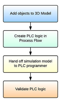
If you'll recall from the Key Concepts About Emulation topic, the following is the basic process for building an emulation simulation project:
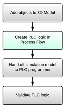
In this topic, you'll learn more about the phase in which you create the PLC logic in a process flow:
Before reading this topic, consider reading the chapter about Conveyors for more information about working with conveyor objects in FlexSim. You might also want to consider completing the Emulation Tutorial if you'd like hands-on experience with the principles discussed in this topic.
Before Starting an Emulation Project
Before starting an emulation project, it will be good to know which kind of protocol your future system will use. Although you can change these settings later, it helps to know which kind of protocol your system will use before you design the PLC logic in process flow.
FlexSim currently supports the following protocols:
- OPC DA
- Modbus TCP/IPv4
- Modbux TCP/IPv6
- Modbus RTU
After you know which type of protocol you're using, it might also be helpful to learn about what kinds of logical inputs it can accept, such as boolean values, strings, numbers, etc. Talking to the eventual PLC programmer about these concerns could help.
Adding Variables
The first step in setting up an emulation project is to add variables to your process flow. Variables are a special type of process flow shared asset that can store different values, reference objects and nodes or take on the functionality of another class. For emulation, Variables can be used as server connections, sensors (PLC inputs) or controls (PLC outputs). See Key Concepts About Emulation - Key Terms for a more comprehensive explanation of the differences between these types of variables.
Adding Sensors (PLC Inputs)
When adding sensor variables to a process flow, keep in mind that sensors will input values from the 3D model and write those values to the server. When you're setting up a sensor, you need to determine which events in the simulation model will change the value for that sensor on the server. Be aware that the range of possible values will depend on the type of server you are using and the types of sensor inputs that are available.
To add a sensor to your process flow:
- With a process flow open and active, add a Variable (under Shared Assets) in the process flow.
- In Quick Properties, click the arrow next to the Variable or Value box to open a menu. Point to Internal Emulation Variable, then point to Sensors (PLC Inputs), then select the type of server you'll use in this project.
- You can tie this variable to an object in the 3D model using the
Associated Object box. You can either sample an object
using the Sampler button
 or select an object from the menu.
 - Under the Write Events group, click the
Add button
 to
open a menu. The menu is context-sensitive and will display the events that are
available for that type of object. Select the event you want to assign a value to.
to
open a menu. The menu is context-sensitive and will display the events that are
available for that type of object. Select the event you want to assign a value to. - In the new event's Value box, type the appropriate value for this event. This value is what will be written to the server.
- Repeat the previous two steps as needed.
Alternatively, you could set up the sensor in the Emulation tool and then link the process flow variable to that sensor in the tool instead. See Using the Emulation Tool for more information.
Adding Controls (PLC Outputs)
When adding control variables to a process flow, keep in mind that controls will output values to the 3D model. Controls only read values from a server; they never write them. When you're setting up a control, you need to determine which actions the control will take when it receives a specific value from the server. Be aware that the range of possible values will depend on the type of server you are using and the types of control output settings that are available.
To add a control to your process flow:
- With a process flow open and active, add a Variable (under Shared Assets) in the process flow.
- In Quick Properties, click the arrow next to the Variable or Value box to open a menu. Point to Internal Emulation Variable, then point to Controls (PLC Outputs), then select the type of server you'll use in this project.
- You can tie this variable to an object in the 3D model using the
Associated Object box. You can either sample an object
using the Sampler button
or select an object from the menu.
- Under the Actions group, click the
Add button to
add a new action.
- In the new action's Value box, type the appropriate value for this action. This value will be what is read from the server.
- Next to the Action box, click the
Add button to
open a menu of picklist options. Select an appropriate picklist for the action you want
the 3D object to take. Then set the properties that are relevant for that picklist
option.
- Repeat the previous three steps as needed.
Alternatively, you could set up controls in the Emulation tool and then link the process flow variable to that sensor in the tool instead. See Using the Emulation Tool for more information.
Adding Server Connections
When adding a server connection, the important thing to keep in mind is whether the server is inactive or active. See Key Concepts About Emulation - Active vs. Inactive Connections for information about the differences.
To set up a server connection:
- With a process flow open and active, add a Variable shared asset (under Shared Assets) to the process flow.
- In Quick Properties, click the arrow next to the Variable or Value box to open a menu. Point to Internal Emulation Connection, then select the type of server you'll use in this project.
- By default, newly created connections will be inactive. This is indicated by
the Active box displaying a
0. - Connect a sensor or control variable to the newly created connection by clicking the
Exclamation Point button
 next to a sensor or control to enter
sampling mode.
next to a sensor or control to enter
sampling mode. - Click the server connection variable you just made to sample it. The variable will now be connected to the server.
- Repeat the previous steps to connect additional sensor or control variables to the server.
Alternatively, you could set up the server connection in the Emulation tool. See Using the Emulation Tool for more information.
Building PLC Logic in a Process Flow
In many respects you'll build the PLC logic in a process flow the same way you would build the logic in any process flow. The Emulation Tutorial provides an example of some of the logic you could possibly build in an emulation project.
When building you can use some additional activities to read from and write to your sensors and controls:
- Set Variable - Use this activity to set the value of an emulation variable when a token reaches this activity in a process flow. You can connect this activity to one of the emulation variables you want to change. You'll indicate the value that the emulation variable should be set to.
- Get Variable - This works similar to a Set Variable activity, but you can use this activity to get the value of an emulation variable when a token reaches this activity in a process flow.
Using the Emulation Tool
You can alternatively use the Emulation tool to set up your connections, sensors, and controls.
Opening the Emulation Tool
You can open the Emulation tool from the Toolbox. The Emulation tool can be found under the Connectivity sub-menu.
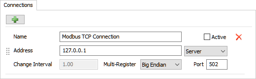
Adding Connections
Use the Connections tab to add a connection. The options that are available for connections are the same ones available for a connection variable in the process flow.
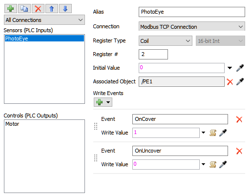
Adding Variables
Then use the Variables tab to add sensors and controls. Again, the options that are available will mirror the same properties that you'll find in the process flow variables.
Linking Process Flow Variables to the Emulation Tool
To link a process flow variable to the emulation tool:
- Make sure the connections and variables have already been set up in the Emulation tool.
- With a process flow open and active, add a Variable shared asset (under Shared Assets) to the process flow.
- In Quick Properties, click the arrow next to the Variable or Value box to open a menu. Point to Emulation Variable, then point to the type of server you set up in the emulation tool, then select the variable you want to link from the Emulation tool.
Alternatively, you can use the Sampler button
next to the
Variable or Value box and click on the emulation tool
in the Toolbox or the connection or variable in the emulation tool window.
Process Flow Instances in Emulation Projects
If desired, you can use the ability of process flows to create instances in an emulation project. Process flow instances might be ideal if you have two or more objects in your 3D model that will use identical logic and might possibly each use identical PLC servers that all have the same logic but with different variables.
For example, perhaps you've got a machine that is a labeler or a packaging machine and it will need an entire PLC dedicated to it. However, you might have 50 of these kinds of machines throughout your system that will run identical logic. You could create a fixed resource object for this labeler and emulate the PLC logic for it using a fixed resource process flow. Then, you'd add copies of this fixed resource object to the 3D model. When the model runs, each fixed resource would run its own instance (copy) of the process flow.
There are a few things you need to consider when working with process flow instances, which will be explained in the following sections:
Global vs. Local Variables
When you are using emulation variables in a fixed resource process flow, you have the option to set their Type property to either global or local:
- Global - Setting the variable type to global will mean that all the instances of that process flow will connect to the same server (for connections) or reference the same variable on the server (for sensors and controls).
- Local - Setting the variable type to local will mean that each instance of that process flow will use its own dedicated server (for connections) or unique variable on the server (for sensors and controls).
Creating Unique Connections
In this section we'll refer to properties of an OPC DA Connection, but the premise is the same for other protocols.
If your connection type is set to Local so that each instance will create a new
connection, you'll need to define the address and server for each instance. If all of the
servers are running on the same computer, then the Address will
remain the same for all connections. In this case, you would make the
Server property dynamic. You could possibly use the code
current.ServerName to get the value of a label on the object.
If the servers are running on different computers, then you'll need to make the Address property dynamic to define a different address for each instance. This could be done in the same way the Server was made dynamic.
Creating Unique Sensor and Control Variables
In this section we'll refer to properties of an OPC DA Tag, but the premise is the same for other protocols.
When you get to the stage in which you are going to validate the PLC logic, you'll need to be able to assign a unique tag ID to each instance of the fixed resource:
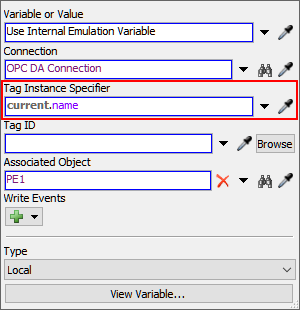
- Set the Tag Instance Specifier - You can use this
property on the variable to set define a unique group or name that will be used to
define the tag ID. To make this property dynamic and adaptable to each instance, you
could possibly use the code
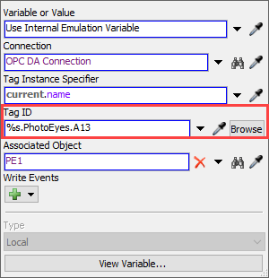
current.nameto get the name of the object. Then you could name each object based on what group they will use. As another alternative, you can set each object to have the same label such as GroupName and then give each object its own unique value. In the Tag Instance Specifier, you'd then use the codecurrent.GroupNameto get the value of that label for each object. - Set the Tag ID - After you've set the tag instance
specifier, you can then reference it in the Tag ID property. You can use the code
%sto dynamically reference the tag instance specifier. Add additional text to define the specific tag ID for the variable. For example,%s.PhotoEyes.A13orPhotoEyes.%sA13
See Process Flow Instances for more information.