Working With GIS Navigation
Introduction to GIS Navigation
You can use GIS maps, points, and routes to define paths that task executers can use to travel with the GIS Navigator. Before reading this topic, you should make sure you are familiar with the concepts discussed in Key Concepts About Travel.
The rest of this topic will provide instructions about how to do the various tasks needed to build a GIS travel network.
Creating Maps
The first step in building any GIS travel network is to add a map to your model.
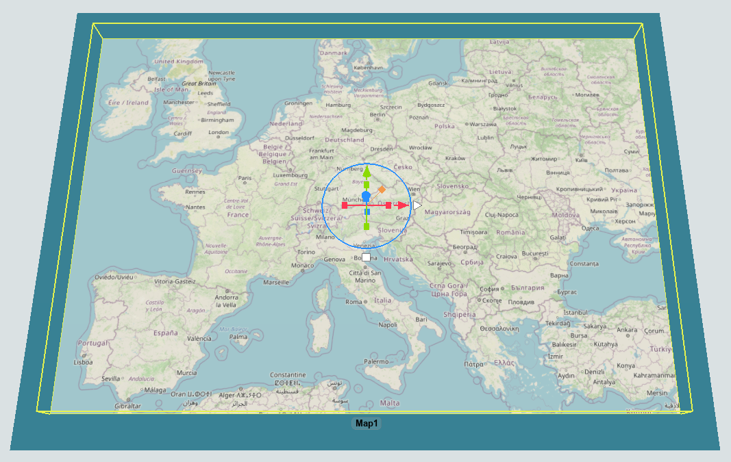
- With the Library open, under the GIS group, drag a Map into your 3D model.
- Select the map and use the mouse wheel to zoom into a particular location on the map. You can use the left mouse button to pan the map's position.
- Move and resize the map to where you want it in your model. Scaling all axes of the map will make the entire map larger or smaller. Scaling just the X or Y axes will adjust how much of the map is drawn at the current zoom level.
Adding and Connecting Points
The next step in building a GIS travel network is to add points to your model and connect them together to form routes:
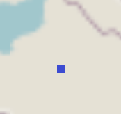
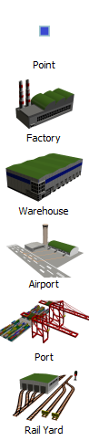
- With the Library open, under the GIS group, drag a Point onto your map. It will appear visually like a square point on the map.
- GIS Points can also have 3D shapes. Click Point in the Library to create points with different shapes. A point's shape can also be changed to any custom 3D shape using the Properties pane.
- You can create routes by connecting points together using the same method you'd use
to create input/output port connections (A-connects) between fixed resources. Click the
Connect Objects button
 on the toolbar to
open a menu. Select Connect Objects from the menu to turn
on connection mode.
on the toolbar to
open a menu. Select Connect Objects from the menu to turn
on connection mode. - When you are in connection mode, your mouse pointer will change to a plus sign with
a chain link symbol next to it:

- Once you are in connection mode, click the first point you want to connect. You will notice as you move your mouse that a yellow line will appear between the point you clicked and your cursor.
- Click a second point to create a route between the two points.
- You will still be in connection mode even after you connect two points together. If you need to exit connection mode, press the Esc key or right-click a blank area in the model. Otherwise, you can continue connecting points together if needed.
Changing Route Types
By default, routes are created as flight paths. You can change their type using Properties or change the default type in the GIS Navigator Properties.
- Create a route between two points using the method outlined in the previous section.
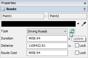
- Click on the route to view its Properties.
- Change its Type to Driving Roads.
- Click the Update button. It may take a moment to download the driving roads information from the routing server. Once the routing data is downloaded, the route will change to driving road paths.
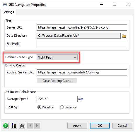
- Right-click the map and select GIS Navigator Properties.
- In the GIS Navigator Properties window, you can change the Default Route Type that is created when connecting points together.
- In the GIS Navigator Properties window, you can also adjust the settings used for air route calculations and specify the Routing Server URL.
Deleting Points and Routes
When you delete a point, it will also remove any routes that are connected to it.
To delete a point:
- Click the point on a map.
- Press the Delete key.
To delete a route:
- Click the route on a map.
- Press the Delete key.
Connecting 3D Objects to the GIS Network
After you've created the travel routes, you can then connect 3D objects in the model to the GIS network.
To connect 3D objects to a GIS point:
- You can connect fixed resources and task executers to a point using the
same method you'd use to connect points together. Click the
Connect Objects button
on the toolbar to
open a menu. Select Connect Objects from the menu to turn
on connection mode.
- When you are in connection mode, your mouse pointer will change to a plus sign with
a chain link symbol next to it:
- Once you are in connection mode, click the point you want to connect to a 3D object. You will notice as you move your mouse that a yellow line will appear between the point you clicked and your cursor.
- Click the fixed resource or task executer to create a connection with the point.
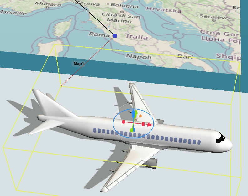
When you connect a task executer to a point, that point will act as the reset point where the task executer will start traveling. When a task executer is connected to a point, it will display a red line between it and the point:
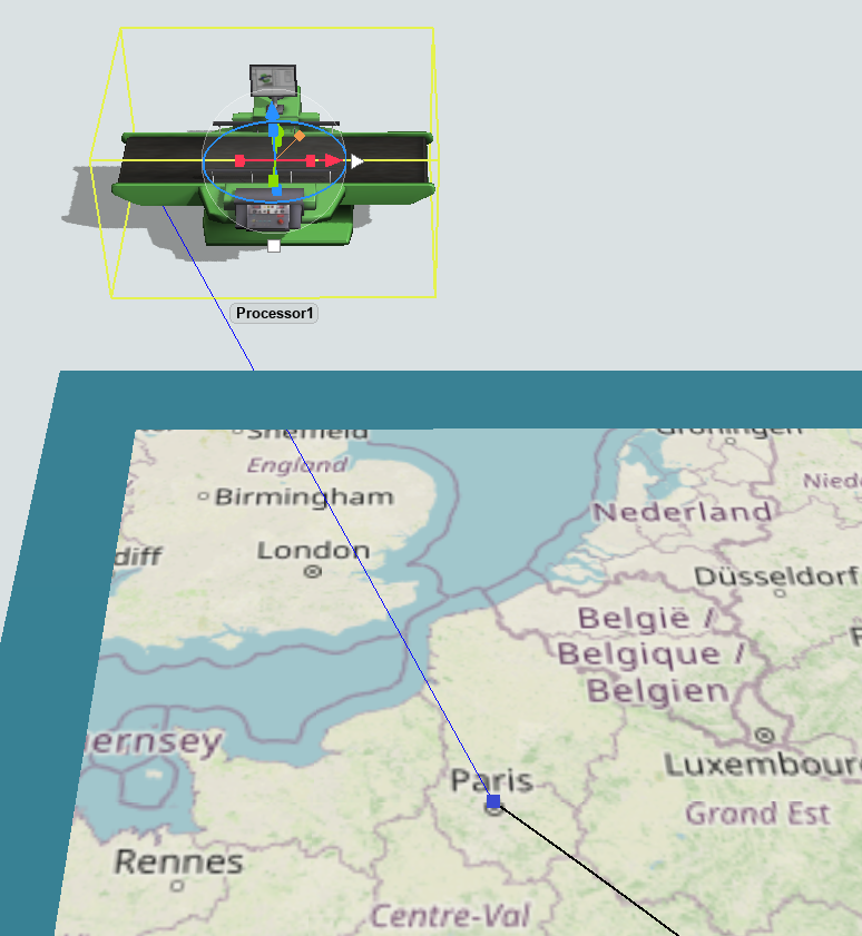
When you connect a fixed resource to a point, that point will make it possible for task executers to travel to that location. Fixed resources can be connected to multiple points. When traveling to a fixed resource, the task executer will travel to the point that is closest to the traveler's current point. When a fixed resource is connected to a point, it will display a blue line between it and the point:
The connection lines are only drawn when the involved objects are highlighted.
- Highlighted travelers will draw a red line to their current point on whatever maps are drawing that point.
- Highlighted fixed resources will a draw blue line to any connected points on whatever maps are drawing those points.
- Highlighted maps will draw red lines and blue lines from any visible points to any involved travelers or fixed resources.
Visualizing Travelers
When task executers are traveling between points using the GIS Navigator, the task executer's 3D shape will not move. Instead, you will see a representation of that traveler's current geographic position drawn on the route on the map. Travelers that are at a point but not currently traveling are not drawn on the map.