Adding and Connecting Activities
Introduction to Adding and Connecting Activities
Activities are the basic building blocks of the Process Flow tool. This topic will explain some important concepts about adding and connecting activities to your process flows. This topic will also explain different methods for adding and connecting activities.
About Connectors and Stacked Blocks
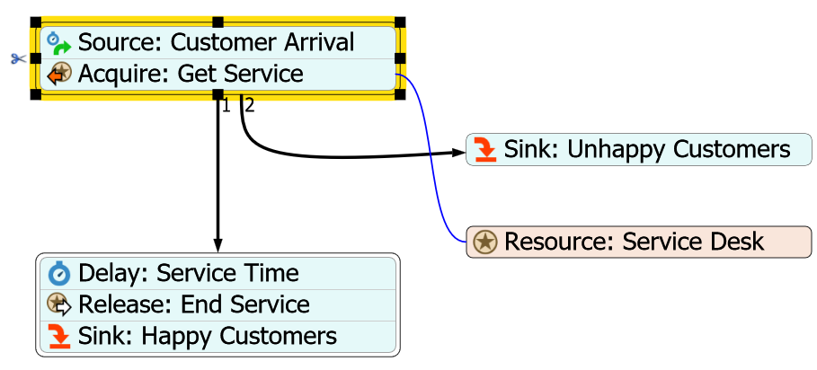
One of the important things to understand are the similarities and differences between connectors and stacked blocks. A connector is a connection between two activities, as shown in the following image:
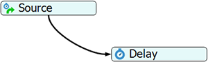
During a simulation run, tokens will use connectors to go from one activity to the next downstream activity. Some activities allow more than one outgoing connector, but many do not.
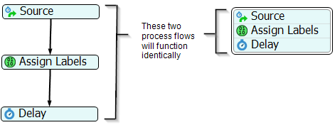
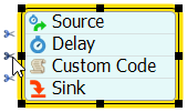
A stacked block is a set of activities that have been snapped together into one movable block, as shown in the following image:
Stacked blocks let you easily link a set of activities into a single sequence of steps, making it easy to move and edit them as if they were one block. When activities are linked together in a stacked block, they are automatically connected as though each activity were connected with connectors. In other words, these two process flows will function identically:
You can create stacked blocks through the object library as explained in Adding Activities from the Process Flow Library or you can drag an activity above or below another activity to snap them together.
Number of Outgoing Connectors
Most activities can only have one outgoing connection because they usually implement a very simple piece of logic on a token. In that case, the activity can simply send the token to the next downstream activity when that logic is complete. However, a few activities can have more than one outgoing connection. For example, a Decide activity can have more than one outgoing connection because tokens might need to be sent to a different downstream activity based on certain changing conditions. To check whether an activity allows more than one connection, read the reference page for the specific activity you're interested in.
You will need to understand how connectors work for activities that can have more than one outgoing connector. The following list explains a few important concepts to keep in mind:
- Each outgoing connection has a number (also sometimes called a rank) based on the order in which you created them. When you create an outgoing connection from one activity to another activity, this connection will automatically be assigned a number (rank). For example, the first outgoing connection you create will be assigned a rank of 1, the second will have a rank of 2, and so forth. You may have noticed that this is similar to how port connections work between objects in the 3D simulation model.
- The token will be sent to the next activity based on the number assigned to the outgoing connector. The underlying logic of the activity depends on the numbers (ranks) of the outgoing connectors. For example, if you wanted to send 75% of tokens to the activity connected to the first outgoing connector, you would send them to connector 1. If you wanted to send 25% to the activity connected to the second outgoing connector, you would send them to connector 2.
- You can re-rank outgoing connectors or assign names to connectors if needed. You can edit the activity's properties to change the ranks of the outgoing connectors or assign a name to a connector. You can also assign a name to a connector for easier reference if needed. (See Changing the Rank Number or Name of Outgoing Connectors for more information.) Activities that allow for more than one outgoing connector will usually have a group of properties labeled Connectors Out that can be used to manage the outgoing connectors. NOTE: If you need to refer to a connector's name in a command of some sort, make sure you put it in quotation marks (" ") so that the FlexSim system can recognize it as a string.
Adding Activities from the Process Flow Library
There are several ways to add activities to a process flow. One way is to add an activity from the Process Flow Library:
- Make sure that the left pane is open to the Library tab (not the Toolbox tab).
- Click somewhere inside a process flow to make the process flow view active. The Library will change to show the process flow activities (instead of the standard FlexSim objects).
- Drag an activity from the Library into the process flow.
If you drop an activity from the library onto another activity within the process flow view, the activities will be joined together by adding the new activity to the end of the block. Dropping an activity in between two activities in a block will insert the dropped activity in between the two activities.
You can also add activities from the library and immediately connect it to a stacked block:
- Drag an activity from the Library into the process flow without releasing the mouse button.
- While holding down the mouse button, drag the activity on top of another activity or stacked block and release the mouse. The activity will be appended to the end of the stacked block.
See Removing Connectors and Separating Stacked Blocks for information about separating stacked blocks if needed.
Adding Activities Using the Quick Library
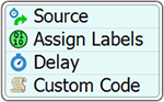
You can also add and connect activities using the Quick Library, which is a condensed menu of the process flow activities, as shown in the following image:
If you want to add an activity to a blank area using the Quick Library inside a process flow:
- Double-click in the process flow to open the Quick Library.
- Click the icon for the activity you want to add.
If you want to add an activity to the end of a stacked block using the Quick Library:
- Point your mouse on the bottom edge of an activity or stacked block. The mouse icon
will change to a chain link.

- Double-click the edge to open the Quick Library again.
- Click the icon for the activity you want to add. The activity will be appended to the end of the stacked block.
See Removing Connectors and Separating Stacked Blocks for information about separating stacked blocks if needed.
Inserting an Activity into a Stacked Block
The Process Flow tool has two methods for inserting an activity into a stacked block, as explained in the following sections.
Adding an Activity from the Process Flow Library
To add an activity inside a stacked block from the Library:
- Drag an activity from the Process Flow library to any area of the process flow.
- While pressing the mouse button, drag the activity into a stacked block to any position in the stacked block. Release the mouse button when it is in its desired position.
Using the Quick Library
To add an activity inside a stacked block using the Quick Library:
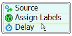
- Point your mouse to the line between two activities until the line turns yellow, as shown in the following image:
- Double-click the line to open the Quick Library again.
- Click the icon for the activity you want to add. The activity will be inserted in the middle of the stacked block.
Moving and Deleting an Activity From a Stacked Block
To move and/or delete an activity from a stacked block:
- Press and hold the Ctrl key. Click the activity you want to move and drag it to a different position in the stacked block. If you want to delete the activity, drag it away from the stacked block to another space in the process flow.
- With the activity still selected, press the Delete key to delete it.
Copying and Pasting Activities or Stacked Blocks
You can easily copy an activity or stacked block. When you copy and paste an activity or stacked block, it will automatically retain all the same settings from the original activity or stacked block. You can also copy activities or stacked blocks from one process flow to another in the same simulation model.
To copy an activity or stacked block:
- Click the activity or stacked block to select it.
- Use Ctrl+C to copy the activity.
- Use Ctrl+V to paste the copied activity.
Images copied from other applications can also be pasted directly into ProcessFlows.
Adding Outgoing Connectors
If you want to create an outgoing connector from one activity to another:
- Point your mouse on the bottom edge of an activity or block. The mouse icon will change to a chain link.
- Click the edge of the activity or block and, while holding down the mouse, drag the mouse toward the activity you want to connect. You'll notice a connector coming from the edge of the block to the mouse pointer.
- Release the mouse when it is connected to the activity. You can change the curvature or position of the connector by clicking on it and manipulating its curve handles if needed.
You can also add a new activity to the end of a connector using the Quick Library:
- Point your mouse on the bottom edge of an activity or block. The mouse icon will change to a chain link.
- Click the edge of the block and, while holding down the mouse, drag it a little bit toward the bottom of the screen. You'll notice a connector coming from the edge of the block to the mouse pointer.
- When you release the mouse, the Quick Library will appear.
- Click the icon for the activity you want to add. The activity will be appended to the end of the stacked block, as shown in the following animated image:
Removing Connectors and Separating Stacked Blocks
To remove a connector:
- Click the connector. It will turn yellow to indicate it is highlighted.
- Press the Delete key. The connector will disappear.
To separate activities in a stacked block:
- Click anywhere inside the stacked block to select it. Its borders will turn yellow to indicate it is selected. You will also notice that some scissor icons will appear to the left in between the activities, as shown in the following image:
- Click the scissors icon between the two activities you want to separate. The stacked block will separate into two different blocks.
Changing the Rank Number or Name of Outgoing Connectors
Certain types of process flow logic might depend on connector rank numbers or names. By default, each outgoing connector is assigned a rank number according to the order in which the outgoing connectors were created. This section will cover changing ranks, adding names, and other related topics.
Viewing Rank Numbers
To view the rank numbers:
- Click an activity to select it.
- If the activity has more than one outgoing connector, the rank number will be displayed next to the connector.
Changing Rank Numbers
To change a rank number of an outgoing connector:
- Click the connector.
- In Properties, use the arrows next to the From Rank or To Rank boxes to increase or reduce its rank numbers.
Adding Connector Names
To change a name of an outgoing connector:
- Click the connector.
- In Properties, in the Name box, type an appropriate name for the connector.
Or:
- Double-click the connector.
- Type an appropriate name for the connector.
The new name will now be displayed in the Process Flow. You can adjust the Font and font size in Properties after clicking the connector name.
Deleting Connector Names
To delete a connector name, click the name and press the Delete key.
Styling Connectors
There are several options for stlying connectors.
Type
The connector Type specifies how the connector should physically connect.
The three connector types are:
- Straight - Draw a straight line between the start and end.
- Bezier - Draw a bezier curve between the start and end.
- Split - Draw a split connection that jumps from one labeled circle to another.
Single or Double
Single or Double specifies if the connector should be drawn with one or two lines.
Width
The connector Width specifies the width of the connector.
Style
The connector Style specifies if the connector is drawn in a solid line or another pattern.
Start Cap and End Cap
Start Cap and End Cap specifies how the start and end of the connector should be drawn.
Color
The connector Color specifies the color of the connector.