Key Concepts About GUIs (Graphical User Interfaces)
Overview and Key Concepts
Graphical User Interfaces (GUIs) are accessed from the Toolbox.
GUIs allow you to create your own window interfaces for your model and its objects. A GUI can communicate with any object in the model, in any way you want.
In FlexSim, GUIs are stored as a node with sub-nodes in the tree. Each node represents a part of your GUI. The attributes in the object data of each of those nodes represent variables that affect how that part of your GUI works. When a GUI is opened, it creates a new node in VIEW:/active that is a copy.
Why Create GUIs?
GUIs are helpful because:
- Not everyone knows how to navigate FlexSim. You can give others the ability to manipulate certain parts of your model without having to know FlexSim.
- Save time on extensive testing. GUIs can help you to change parameters quickly in your model during the testing process.
- GUIs look professional.
GUI Views
FlexSim GUIs are made up of building blocks called views. Views are windows that perform specialized roles and can be combined hierarchically. These views will allow you to view and manipulate data in the FlexSim tree structure. Since data takes many forms, there are many types of views.
Below is a list of the View Types available in FlexSim. The number next to each view type is the viewwindowtype. This number is a direct reference to the type of view and will not change in future releases of FlexSim.
Windows Common Controls
| View Window Type | Value |
|---|---|
| Static (or label) | 103 |
| Button | 100 |
| Radiobutton | 106 |
| Checkbox | 105 |
| Edit | 101 |
| Trackbar | 122 |
| Combobox | 109 |
| Listbox | 114 |
| Tabcontrol | 115 |
| Scrollbar | 104 |
| Statusbar | 110 |
| Spinner | 123 |
| DateTimePicker | 125 |
| Treeview | 119 |
FlexSim Registered Controls
| View Window Type | Value |
|---|---|
| Dialog | 4 |
| Panel | 102 |
| Groupbox | 107 |
| Table | 5 |
| Graph | 6 |
| 3D View | 2 |
| Tree | 0 |
| IconGrid | 7 |
| Script | 8 |
| HTML | 124 |
Designing a GUI
There are whole books written about the philosphy of GUI design. The major topic, ease of use. Avoid the temptation of making a GUI window try to do too much. GUIs should be simple to navigate and focused in their function.
It is recommended to sketch out what you want a GUI window to look like before you open the GUI editor.
GUI Building Tips
It is important to have a good Control naming convention. A good short name will make referencing the object in code much easier.
Use Panel controls (invisible and not invisible) to group, move, and copy sections of your GUI.
GUI building essentially consists of adding views to your GUI window and giving those views the appropriate attributes. While the "View Specific" option of the attribute list gives you some good hints of which attributes are appropriate to add, there are also other ways you can become more comfortable and experienced building GUIs.
Another way you can become more familiar with building GUIs is by simple experimentation. Add an attribute that you've never added or seen before and see how it affects the GUI. If there is no change, then either the attribute doesn't do anything for this type of view, or it's somehow not implemented right. Fiddle around with different settings and values for the attribute to see if and how it changes the GUI. If still nothing changes, then just move on and try something else. If it does, great! That's one more tool that you have in your knowledge base.
Practice, practice, practice. As you continue to build more and more GUIs, the speed and efficiency with which you do it will increase significantly, and you will be able to get a feel for what GUI styles are more user friendly.
Working with the GUI Editor
Here are some tips with working with the GUI editor:
- Think about not only how to arrange the controls in the GUI canvas (window editor) but also in the tree. Having familiarity with the Tree is a requirement for good GUI building.
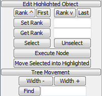
- Moving controls in the tree can be done using the Edit Highlighted Object and Tree Movement fields in the GUI builder window.
- The attribute nodes of the GUI controls define how the control will look/behave. Each control has a default set of attribute nodes but others can be added from the Controls palette on the GUI builder window.
Traversing the Tree
@ - This symbol tells the traversal to go to the owner view of the current node. For this coldlink node, it is the main GUI window.
> - This symbol tells the traversal to go into a node's attribute tree.
+ - This symbol tells the traversal to read the current node's text as a path to an object, and go to that object.
/ - This symbol tells the traversal to go into the current node's sub-tree.
.. - This symbol tells the traversal to go to the current node's parent tree, or up one level.
? - This symbol causes a recursive tree search for the subsequent name. For example, node("/?FlowItemBin", model()) will search for a node with the name FlowItemBin in the model tree. This returns the same node reference as an explicit path definition would: node("/Tools/FlowItemBin", model()).
$flexscript$ - This syntax allows you to enter in custom
flexscript code when accessing the path. For example, if you had a Global Macro
#define MY_NODE_RANK 4 then having a path of
>objectfocus+/$MY_NODE_RANK$ would be read as >objectfocus+/4. You
can execute any valid flexscript code. Another example, if you have an object in the model
with a label called focus that contains "Tool4", then the following path
>objectfocus+/$getlabel(node("MyObject", model()), "focus")$ would be read as
>objectfocus+/Tool4.
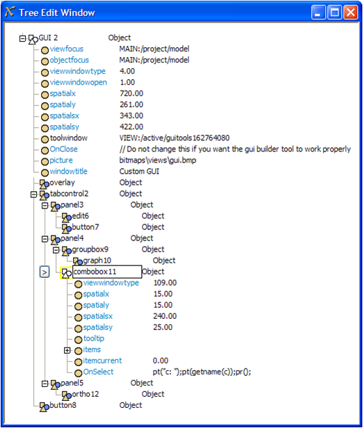
Below is a example table for Tree Referencing (Tree shown below table)
| Code | Returns |
|---|---|
| c | combobox11 |
| itemcurrent(c) | itemcurrent |
| node(">itemcurrent",c) | itemcurrent |
| ownerobject(c) | panel4 |
| node("..",c) | panel4 |
| node("../../panel5/ortho12",c) | ortho12 |
| ownerview(c) | GUI 2 |
| node("@",c) | GUI 2 |
| node("@>toolwindow",c) | toolwindow |
| node("@/tabcontrol2/panel3/1",c) | edit6 |
| node("../../3/1",c) | ortho12 |
| node("@/button8",c) | button8 |
| node("@>objectfocus+",c) | model |
Attribute Lists
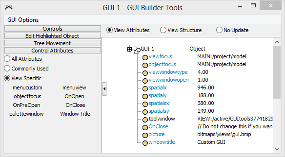
The list of possible attributes to the left of the GUI builder's tree view has three options for viewing attribute lists. They are: all attributes, commonly used attributes and view specific attributes.
All Attributes
If this option is selected, all possible attributes are displayed. Usually you will not need to use this option.
Commonly Used
If this option is selected, a list of commonly used attributes will be shown. These include things like alignment attributes, which allow you to anchor a view's position or size to the right or bottom of its container view.
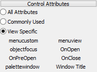
View Specific
This option is the default option. If it is selected, then the attribute list that is shown will be specific to the type of view, or view, that you are currently editing. If you click on a button view, an attribute list will appear that is specific to a button. This includes an OnPress attribute, which is executed when the button is pressed. A label view will have a different set of attributes that are used for it, etc.
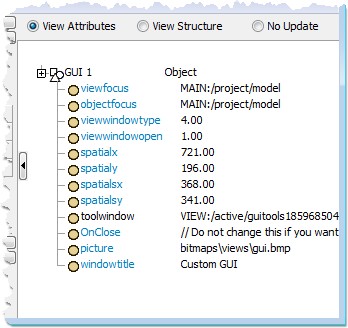
Tree View - Viewing Attributes vs. View Structure
The GUI builder's tree view also has two options for viewing the tree. They are: view attributes and view structure.
View Attributes
This option will view the attributes of the currently selected view.
View Structure
This option will view the tree structure of the currently selected view. This is useful for rearranging and editing the structure of the GUI's tree.
No Update
This option will cause the GUI builder to not update the tree focus when you click on a control in the gui canvas. Some users prefer this as it doesn't change the view every time you click in the canvas.
Linking to the Model
FlexSim uses two types of linking when tieing a GUI object into the model. Coldlinks, and hotlinks.
coldlinks
A coldlink attribute tells the view's text field to be linked to a certain node in the object's attribute tree. The link is "cold" because it gets the value only once when the window opens, and sets the value only when an apply button is pressed.
Example: On the Processor tab of the Processor, the Max Content field is an example of a coldink.
hotlinks
A "hot" link, on the other hand, would continuously update its text field as the value in the model changes.
Example: On the statistics page of the Processor, the Content statistics are examples of a hotlink.
hotlinkx/coldlinkx
Similar to the above, but rather than using a special string of characters, FlexScript code is allowed to establish the link. The "c" passed in as argument 2 of the below example represents the owner object of the attribute.
Example: return(node("@>objectfocus+",c));
Copy an Existing GUI
If you see a window view or GUI that you want to copy verbatim from an existing window to your GUI there are two ways to copy.
Copy from Tree
Find that view in the tree, right click on it and select "Edit > Copy"
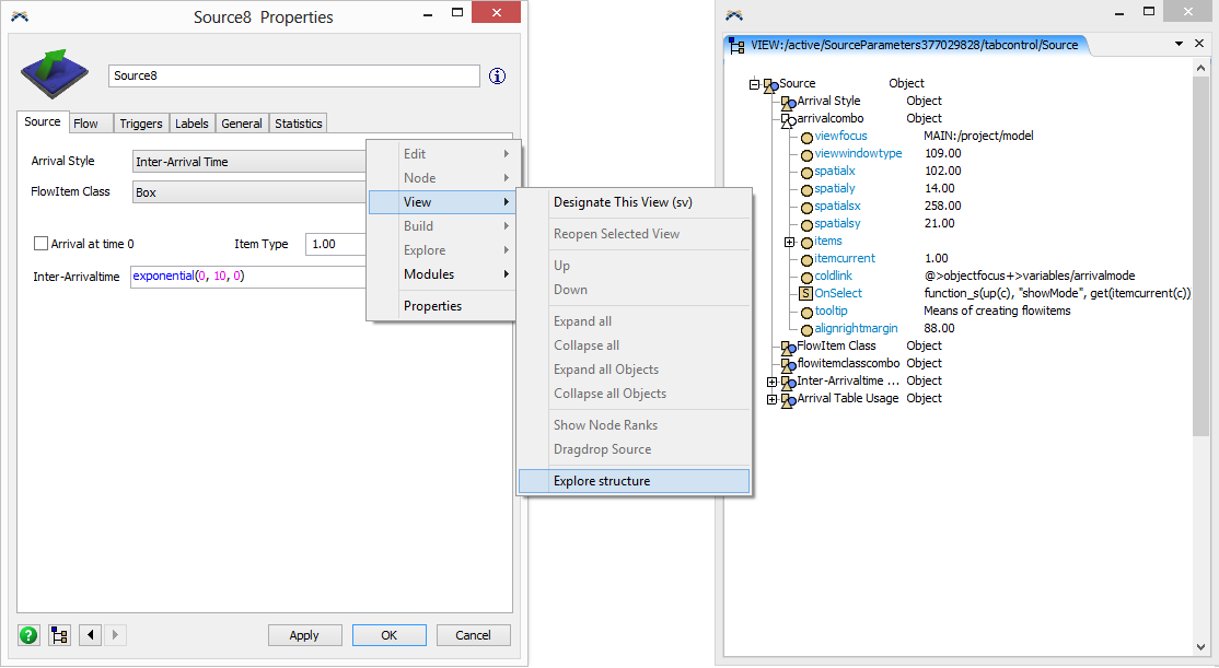
Copy from Window
Open up the window you want to copy. Right click on it, and select "View > Explore Structure" from the popup menu. This will open a tree window that shows the structure of the window. From here you can view the attributes of that window to see which attributes are present, so that you can add those attributes to your own GUI. Right click on the view node and select "Edit > Copy"
Now go to your own GUI's tree structure. In the GUI's tree structure, create a new blank node by right clicking on the container view you want to place it in, and select "Node > Insert Into". Then right-click on the new blank node, and select "Edit > Paste". This will paste the view into your GUI. Press F5 to refresh the view with its added view.
Building a GUI
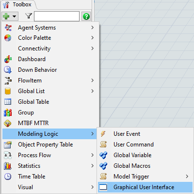
Add a GUI by pressing the add button in the Toolbox and then Modeling Logic > Graphical User Interface.
Once you have added a GUI, two windows will open. The window on the left is called the GUI builder. This window provides you with several tools for building your GUI.
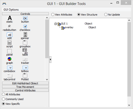
The window on the right is called the GUI canvas. This window shows what your GUI looks like. Initially it is blank. We will add GUI views to it in a drag-drop fashion from the GUI builder window.
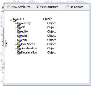
As an example, we will create a simple GUI that allows you to edit the max speed, acceleration, and deceleration variables of an Operator object. First, let's drag a few simple views onto our GUI canvas. From the top panel of the GUI builder, drag a button onto the GUI canvas.
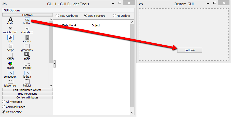
You can now select the button by clicking on it. When the button is selected, you will see a dotted outline around it, as well as a black square to the bottom right of it.
To move the button, just click and drag the button to the location you want it at. To change the size of the button, click and drag the black square.
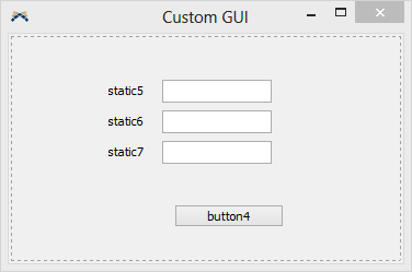
Now add three static views and three edit views onto the GUI canvas, as shown below.
Change View Names
Now we want to change the names and attributes of our GUI views. Collapse the controls toolbar by pressing on the "Controls" button in the gui builder. First, let's make the button an OK button that will apply the edits the user has made, and then close the window. Click on the button. Then click on the "View Attributes" radio button in the gui builder window. Notice that the button and its attributes are now shown in the tree view of the GUI builder.
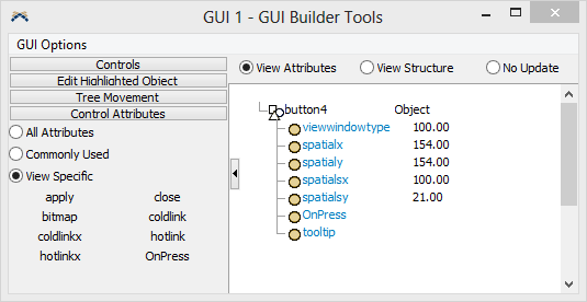
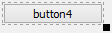
Click on the button name ("button4" in our case) and rename it to "OK". On the left are some commonly used attributes that can be added to the button. To add an attribute, just drag it from the icon grid on the left to a blank area in the tree view.
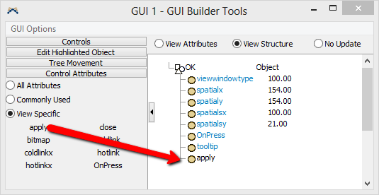
Add an apply attribute and a close attribute to the button. The apply attribute causes all coldlinks and hotlinks found in the view to be applied to their respective destination nodes when the button is pressed. Coldlinks and hotlinks will be explained later. The close attribute causes the window to close when this button is pushed.
Now click on the first static view. Again, the static view and its attributes should appear in the tree view of the GUI builder. For the name of the first static view, enter "Max Speed". You will not see the name change on the static view until the view is refreshed. Now click on the second static view and set its name to "Acceleration". Then click on the last static view and change its name to "Deceleration".
Now that you have made a few changes to the GUI views we will refresh the GUI canvas to see these changes. Click on the GUI canvas window and then press the F5 button. This will change the GUI canvas from editing mode to regular viewing mode. Now your window should look like a normal window without the dotted lines around it.
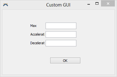
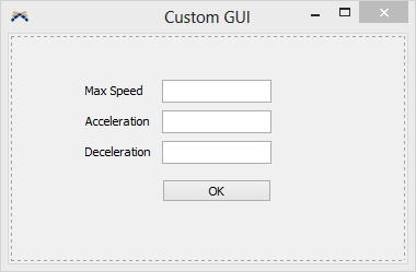
Notice that the label views are now not large enough to fit the text that they are showing. To fix this, go back into editing mode by selecting the GUI canvas window and pressing F5 again. Now rearrange the sizes and locations of your views so that there is enough room to show the entire text of the labels.
Link the Edit Views
Now let's connect the edit views up to their proper nodes in the model. First let's explain some concepts. Click in a blank area in your GUI canvas. This will cause the tree view of the GUI builder to show the attributes of the main GUI window.
Notice that there is an attribute called objectfocus. Right now this attribute shows the path "MAIN:/project/model". Later on, though, once you've associated an Operator with this GUI, and then double-click on the Operator to open this window, the objectfocus attribute will be changed. It will specify a path to the Operator you are editing. For example, you've associated an Operator named Bob with this GUI. When you double-click on Bob, an instance of this GUI is created, and its objectfocus attribute is set to the string path: "MAIN:/project/model/Bob". This is important to know when creating edit fields that are linked to our object. Now let's go back to the first edit field.
Click on the first edit view to view its attributes in the tree. Add a coldlink attribute from the list on the left.
Now enter the following as the text of the coldlink attribute: @>objectfocus+>variables/maxspeed
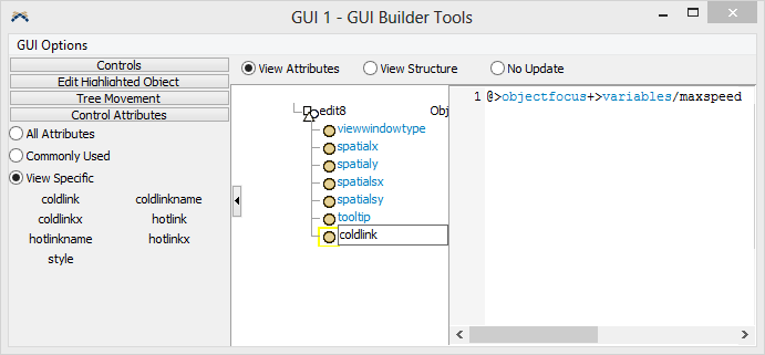
Links should be made to a node that contains some desired value. Sometimes linking directly to the object property node is undesireable, such as code nodes. In this case, link to a label and use the label value as part of the code property (use executestring()).
The coldlink/hotlink text specifies a path to a node that the edit field is to be associated with. This path starts at the coldlink node itself, and should specify a path to the maxspeed variable node on the operator. The different symbols in the path are ways of specifying how to traverse the tree to the destination node.
The coldlink you have specified does the following:
- Starting at the coldlink node, go to its ownerview, or the main GUI window (@).
- From there, go into its attribute tree and find the attribute named objectfocus (>objectfocus).
- Interpret the text of the objectfocus node as a path to a node, and go to that node (+). Remember that when we open this window for our Bob operator example, the objectfocus attribute will be changed to "MAIN:/project/model/Bob". So it will now go to our Bob operator in the model.
- From there, go into the object's (Bob's) attribute tree, and find the node name variables (>variables).
- From there, go into the node's sub-tree and find the node named maxspeed (/maxspeed).
Now connect the other two edit views. Click on the second edit view, then in the tree view add a coldlink attribute and specify its text as: @>objectfocus+>variables/acceleration. Do the same for the last edit view and set its coldlink attribute to: @>objectfocus+>variables/deceleration.
Direct Model Objects to This GUI
Now that we've finished creating our GUI, let's direct an operator in our model to this GUI. Drag an operator into your model. Select it by holding Control or Shift down and clicking on the operator.
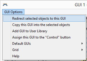
Now go back to the GUI builder window, and from its menu, select "GUI Options > Redirect Selected Objects to this GUI".
This will redirect all selected objects in the model to use this GUI instead of their usual properties window. Now close the GUI builder window. This will automatically close the GUI canvas window as well. Now double click on the operator you have selected. This will open the GUI window you have designed instead of the normal properties window.
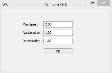
Make some changes to the max speed, acceleration and deceleration values, then press the OK button to apply those changes. Open the window again to verify that your changes were applied correctly.
Gui Builder Menu
The GUI builder's edit menu allows you to do several operations with the GUI once you have created it.
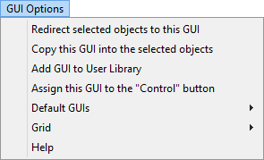
Redirect Selected Objects to this GUI
This option will redirect the guifocusclass attribute of every selected object in the model to point to this GUI. To illustrate this, explore the model tree, and find the operator that you redirected to the GUI you created. Expand its attribute tree and the expand the node named "special". Inside of special there should be a node named guifocusclass. This node's text specifies a path to a window that will be opened when the object is double clicked on.
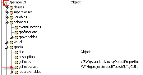
Notice that the path for this attribute is "MAIN:/project/model/Tools/GUIs/GUI 1". This is where our GUI is stored. When we selected the redirect option, it changed this path from the Operator's normal Properties page to our page.
Copy this GUI into Selected Objects
This option will create a complete copy of the GUI and store it inside of each selected object. Go back into the toolbox and open the GUI builder and GUI canvas for the GUI you've built. Then, with our original operator still selected, select the menu option: Edit > Copy this GUI into Selected Objects. Now go back into the model tree view and look at what was done with the operator's guifocusclass attribute.
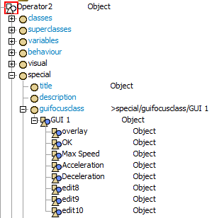
Now the guifocusclass attribute has been changed to ">special/guifocusclass/GUI 1". Also, a copy of the entire GUI that we created has been copied into the guifocusclass attribute.
Although you will not need to use the "Copy this GUI into Selected Objects" option if you are just using this GUI for this model, it is useful for portability purposes. Once you have created this GUI and copied it into the object, you can add the object to a user library, and then drag it into other models, and the GUI will be created with it.
Add GUI to User Library
This option will add the GUI to the selected user library in the library icon grid. For more information on user libraries, refer to the user library documentation.
Assign this GUI to the "Control" button
This option causes the "Control" button on FlexSim's main toolbar to open this GUI when it is pressed. This button is called the Model Control GUI button. Its exclusive purpose is to allow model builders to define custom GUIs for controlling models and their properties without having to change FlexSim's view tree. If this button is no longer available, you may add it to your user toolbar through the Global Preferences Window.
Default GUIs
This sub-menu lets you also edit how other buttons on FlexSim's main toolbar operates. The 3D View button on the toolbar can be customized to open custom GUIs that you have created. By selecting "Make this GUI the Default 3D View GUI" you can cause the 3D View buttons on the main toolbar to open your GUI. Select "Reset Default 3D View GUI to Original" to cause the 3D View buttons to revert back to their original GUIs. Note that making a custom GUI for the 3D View buttons only applies to the model you are editing. When you open another model, the 3D View buttons will reset to the original default view.
Grid
This sub-menu lets you set whether the GUI canvas snaps to grid and what that grid size is.