Task 4.3 - Using Elevators With AGVs
Task Overview
In this tutorial task, you'll learn how to use elevators to transport AGVs to multiple floors in a model. However, before you do that, you'll create four new flow items: one for medical supplies, clean laundry, dirty laundry, and waste. You'll learn to send AGVs to different types of locations based on the type of load it is carrying. You'll also modify the delivery schedule so that medical supplies and clean laundry will arrive at the unloading dock on an alternating schedule.
After creating the flow items and updating the delivery schedule, you'll create upper floors to the hospital that will each need to receive shipments of medical supplies and clean laundry. You'll add an elevator to the simulation model to transport AGVs between the different floors. In the last step, you'll learn how to modify the simulation model to add additional elevators.
Just like in the previous tutorial task, you will use an AGV elevator process flow template to create the logic for this model. Again, it is beyond the scope of this tutorial to explain the exact details of how the AGV elevator template works, you should be aware that this process flow will control nearly all of the logic in this AGV elevator system. Consider exploring the AGV elevator process flow template in more detail to learn how it works. The template is organized by function and is self-documented to help you understand it.
When you're finished, your model will look similar to the following image:
Step 1 Create New Flow Items
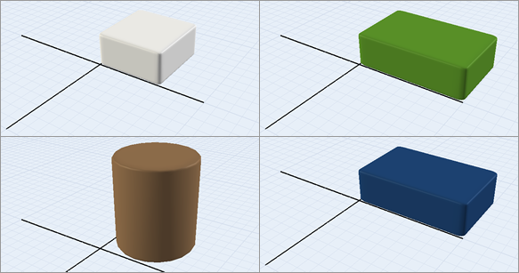
In order to demonstrate the sophisticated way in which AGVs can deliver different types of loads to different locations, you're going to create some custom flow items in this step. These custom items that will be transported to various destinations in the simulation model. You'll create flow items for medical supplies, clean laundry, dirty laundry, and waste:
To create these new flow items:
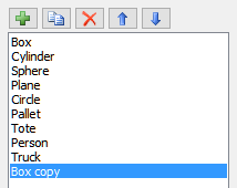
- In the Toolbox, expand the FlowItem Bin group. Double-click the Box to open that flow item in the Flow Item Bin.
- In the Flow Item Menu, make sure that
Box is currently selected, then click the
Copy button
 to create a copy of the Box flow
item.
to create a copy of the Box flow
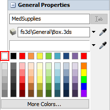
item. - In Properties, change the name of this flow item to MedSupplies.
- Change the Color to white.
- With this flow item still selected in the Flow Item
Menu, click the Copy button
to create a copy of it.
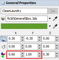
- In Properties, change the name of this flow item to CleanLaundry.
- Change the Color to green.
- Change the X-size to
0.60and the Y-size to1.0. - With this flow item still selected in the Flow Item
Menu, click the Copy button
to create a copy of it.
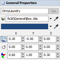
- In Properties, change the name of this flow item to DirtyLaundry.
- Change the Color to dark blue.
- In the Flow Item Menu, select the
Cylinder. Click the Copy
button to create a copy of it.
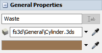
- In Properties, change the name of this flow item to Waste. Leave all the other properties at their default.
Consider saving your simulation model at this point.
Step 2 Change the Delivery Schedule
In this step, you'll modify the DeliverySchedule process flow so that the Unloading Dock will regularly receive two types of flow items: medical supplies and clean laundry. In this hypothetical scenario, the unloading dock will receive a shipment of 10 units of medical supplies every 30 minutes. 15 minutes after the unloading dock receives that shipment, the unloading dock will receive a shipment of 10 units of clean laundry. It will then repeat on this schedule indefinitely.
You'll start by editing the DeliverySchedule process flow activities. The following is an overview of how each activity will function after you've edited them:
| Activity | Explanation |
|---|---|
| Source: MedSupplies Deliveries | The Schedule Source is an activity that will create tokens at a specific time during a simulation model. You'll edit this activity so that it creates 10 tokens when the simulation starts, and then repeats that schedule every 30 minutes. In order to create this functionality, you'll need to add an additional row that will release 0 tokens 1800 seconds later (the equivalent of 30 minutes in the simulation model). |
| Create Object: Item at Unloading Dock | You'll edit this activity so that it will create the new MedSupplies flow item and place it inside the UnloadingDock queue. You'll also add a label named LoadType to the new flow items that will indicate which type of flow item it is. You'll use a value of 1 for MedSupplies flow items. |
After you've made these edits, you'll create a copy of this activity block and modify it to create Clean Laundry deliveries. You'll make a few edits to the activities:
| Activity | Explanation |
|---|---|
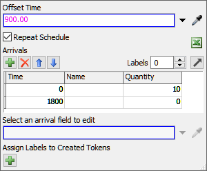
| Source: Clean Laundry Deliveries | This Schedule Source activity will be identical to the MedSupplies Deliveries, except that it will be offset by 900 seconds (the equivalent of 15 minutes in the simulation model). The time offset will make it so that the deliveries alternate every 15 minutes in the simulation model. |
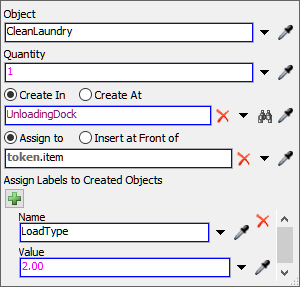
| Create Object: Item at Unloading Dock | You'll edit this activity so that it will create the new CleanLaundry flow item and place it inside the UnloadingDock queue. You'll also edit the label named LoadType to use a value of 2 for CleanLaundry flow items. |
To make these changes to the delivery schedule:
- Open the DeliverySchedule process flow.
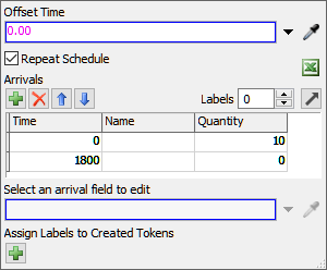
- Click the Source: MedSupplies Deliveries activity to select it. In Properties, check the Repeat Schedule checkbox.
- Under the Arrivals table, click the
Add button
 to add a second row.
 - In the second row under the Time column, type
1800. - In the second row under the Quantity column, change the
quantity to
0. - Click the Create Object: Item at Unloading Dock to select it. In Properties, click the arrow next to the Object box to open a menu. Point to Flowitems, then select MedSupplies.
- Under the Assign Labels to Created Objects, click the
Add button
to add a label.
- In the Name box, delete the current text and type
LoadType. - In the Value box, delete the current text and type
1.00. - Click the Medical Supplies shape to select it. Press Ctrl+C to copy the shape. Click a blank area in the process flow and press Ctrl+V to paste the shape.
- Change the name of the copied shape to Clean Laundry.
- In the Clean Laundry shape, change the name of the Source: MedSupplies Deliveries activity to Source: Clean Laundry Deliveries.
- Click the Source: Clean Laundry Deliveries activity to
select it. In Properties in the Offset Time box, type
900.00. - In the Clean Laundry shape, click the Create Object: Item at Unloading Dock to select it. In Properties, click the arrow next to the Object box to open a menu. Point to Flowitems, then select CleanLaundry.
- Under the Assign Labels to Created Objects, click the
Add button
to add a label.
- In the Name box, delete the current text and type
LoadType. - In the Value box, delete the current text and type
2.00.

Reset and run the model:
As you watch the model, the medical supplies are delivered right when the model starts. 15 minutes later, the clean laundry is delivered. Be aware that the model run in the previous image is being run at a speed of 40.00 and there is an edit cutting out the time between deliveries.
Step 3 Create an Upper Floor Layout
In this step, you'll create three floors to which the AGVs will travel to deliver the medical supplies and clean laundry. For this model, you won't create floors that are stacked vertically on top of each other. Rather, you will create different floor sections and place them on the same plane as the main floor of the AGV model. The stacked floor model has the advantage of looking a little more realistic. However, keeping the floors on the same plane has the advantage of being much easier to work with. See Creating Multiple Floor Layouts for more information about working with multiple floors in AGV models, including links for more information about how to create stacked floor models.
You'll need to create a Next Work Point loop on each floor. As you'll recall from the previous tutorial task, a Next Work Point loop is basically a series of control points that are connected to each other in a loop. Once this circuit has been set up, the AGVs in the system will loop continuously through the network looking for transportation tasks to work on. You need to create a Next Work Point loop on the upper floors in order for the AGVs to keep looping through that floor and to return to the main AGV network when they're finished with transportation tasks.
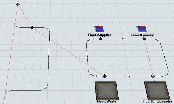
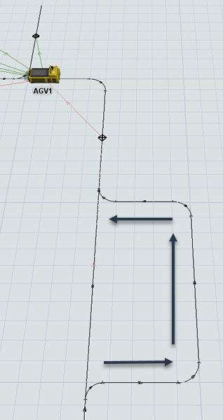
When you're finished, your model will look similar to the following image:
To create an upper floor layout:
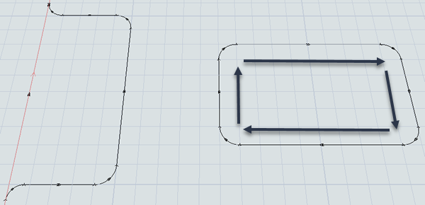
- You'll start by creating an elevator area. Create a series of AGV paths extending out from the center right side of the AGV network that is 5 units long on the x-axis and 10 units long on the y-axis. Make sure that the path directions flow in the same direction as the main AGV network.
- Next, you'll create a network for one of the upper floors. About five spaces out from the new elevator area you just created, create a looping series of AGV paths that is 10 units long on the x-axis and 6 units along the y-axis. Set the path directions to flow clockwise.
- From the library, add 2 Sinks, placing them above the new floor area.
- Add 2 Queues, placing them below the new floor area.
- For clarity, rename the new objects as follows:
- Add four Control Points, placing them on the paths for the new floor area near each object.
- Create location connections (A-connects) between the four objects and the control point near it on the path.
- Add one more Control Point to the upper path in the elevator area.
- For clarity, rename this control point ElevatorExit.
- Create a connection (A-connect) from the control point near the Floor3Supplies sink to the control point near Floor3Laundry to open a menu. Select NextWorkPoint. A red line will appear showing the second AGV is connected.
- Repeat the previous step to create looping next work point connections between
the new control points in the following order:
- From the control point near the Floor3Laundry sink to the control point near the Floor3DirtyLaundry queue
- From the control point near the Floor3DirtyLaundry queue to the control point near the Floor3Waste queue
- From the control point near the Floor3Waste queue to the ElevatorExit control point
- From the ElevatorExit control point to the control point on the upper right corner on the main AGV network
| Object | New Name |
|---|---|
| First Sink | Floor3Supplies |
| Second Sink | Floor3Laundry |
| First Queue | Floor3Waste |
| Second Queue | Floor3DirtyLaundry |
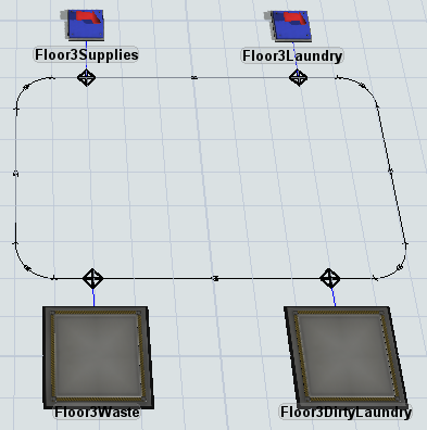
Check that your model looks similar to the image at the beginning of this step.
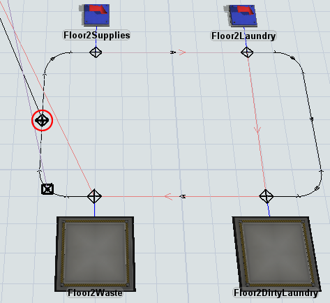
Step 4 Add Upper Floor Destination Logic
Now that you've created the basic template for one of the upper floors in your 3D model, it's time to set up the logic for these objects. In this step, you'll set the sinks on the upper floors to pull flow items from the ItemsReadyForDelivery global list using the LoadType label. You'll set the Floor3Supplies sink to pull medical supplies (which have a LoadType value of 1) and the Floor3Laundry sink will pull clean laundry (which has a LoadType value of 2). You'll also set the Floor3Waste and Floor3DirtyLaundry queues to automatically push any flow items they contain to the ItemsReadyForDelivery global list.
After you've set up this logic, you'll create copies of the upper floor objects to add two additional floors. You'll also create a two-way AGV path connecting the path from the elevator area to each of the upper floors. You need to create this path so that the AGV network needs to be able to find a travel path from one floor to another.
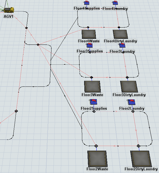
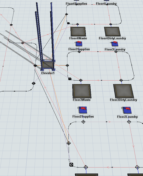
When you're finished, your model will look similar to the following image:
To create this logic:
- Click the Floor3Supplies sink to bring up its properties on the right.
- Under the Input tab, check the Pull Strategy checkbox.
- Click the arrow next to the Pull Strategy box to open a menu. Point to Use List and select Pull from Item List to open a picklist window.
- Click the arrow next to the List box to open a menu and select ItemsReadyForDelivery.
- Next to the Query box, click the
Add button
to open a menu. Point to WHERE (filter) and select
LoadType.
- In the Query box, change the last part of the list
query to
== 1. - Repeat the previous steps for the Floor3Laundry sink,
but instead change the last part of the list query to
== 2. - Click the Floor3Waste queue to bring up its properties. Under the Output section, click the arrow next to the Send To Port box to open a menu. Point to Use List, then select Push to Item List.
- Click the arrow next to the List box and select ItemsReadyForDelivery.
- Check the Use Transport box. Click the arrow next to this box to open a menu. Point to Use List, then select Push to Item List (no task sequence) to open a picklist window.
- Check that the List box shows that the AGVWork list is currently selected. Leave the rest of the properties on their default settings.
- Repeat the previous steps for the Floor3DirtyLaundry queue as well.
- Press and hold the Ctrl key and draw a box around the entire new floor area you created to select these objects (including both sinks, both queues, and the AGV paths). Press Ctrl+C to copy these objects. Press Ctrl+V to paste a copy of these objects.
- Move the copied objects to that they are just below the original objects (but still on the same plane).
- Rename each of the newly copied 3D objects replacing any 3 numbers with the number 2: Floor2Supplies, Floor2Laundry, Floor2Waste, and Floor2DirtyLaundry.
- Repeat the previous step to create a third copy of the original objects. Move these copied objects just above the original objects (but still on the same plane).
- Rename each of the newly copied 3D objects replacing any 3 numbers with the number 4: Floor4Supplies, Floor4Laundry, Floor4Waste, and Floor4DirtyLaundry.
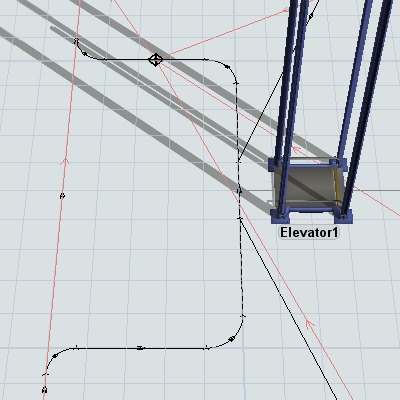
- Create an AGV path extending from the elevator area that is connected to one of the three upper floor areas.
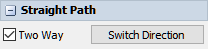
- Select the new path you created. In Properties, check the Two Way check box.
- Repeat the previous steps to add two-way AGV paths to the other two floors.
Reset and run the model:
As the model runs, you'll see that AGVs travel to the upper floors to drop off flow items at the various sinks. Different sinks receive different flow items based on their LoadType label.
As was mentioned in the introduction to this step, you need the two-way AGV paths in order for the AGVs to travel to the upper floors. After you add the elevator in the next step, the AGVs will not use these paths to move between the floors. However, you still need these paths to be present in order for the AGV network to calculate a possible path to the upper floors.
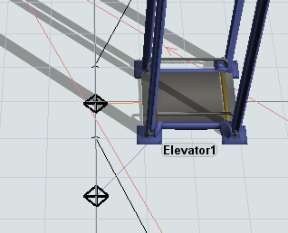
Step 5 Add an Elevator
In this step, you'll add an elevator to the model and create a new process flow to control this elevator using the AGV Elevator process flow template. In the last part of the step, you'll attach the new elevator to this process flow.
When you're finished, your model will look similar to the following image:
To add an elevator to the AGV model:
- From the Library, add an Elevator to the 3D model, placing it in between the elevator area and the upper floors.
- On the main toolbar, click the Process Flow button to open a menu. Point to Add an Object Process Flow and then select AGV Elevator.
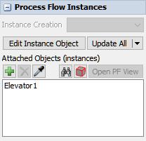
- In the newly created process flow template, click a blank area to ensure nothing is selected.
- In Properties under the Process Flow Instances
find the Attached Objects (instances) box. Click the
Sampler button
 to enter sampling mode.
 - In the 3D model, click Elevator1 to attach it to the process flow template.
- Close the process flow template.
Check that your model looks similar to the image in the beginning of this step.
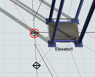
Step 6 Add Elevator Redirect and Entry Control Points
In this step, you'll set up the control points on the ground floor and upper floors that they will interact with the AGVs and the process flow to use the elevator to move between the floors.
You'll start by adding elevator redirect control points and connecting them to the elevator. Elevator redirect control points handle requests for elevator transport. When an AGV passes over the redirect control point, it will attempt to acquire an elevator for transport. If one is available, it will then proceed on the path until it reaches an elevator floor control point. If an elevator is not available, it will wait at this control point until an elevator is free.
After you've added the elevator redirect control points, you'll add elevator floor control points. Elevator floor control points become the point where AGVs enter and exit the elevator on each floor. When an AGV passes over an elevator floor control point, it will appear inside the elevator. When an AGV exits an elevator, it will appear on the elevator floor control point.
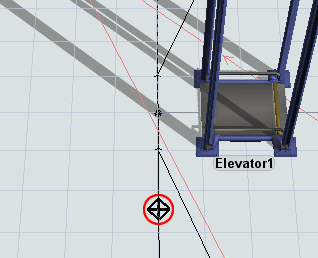
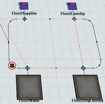
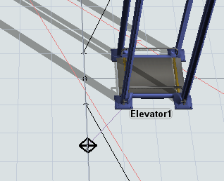
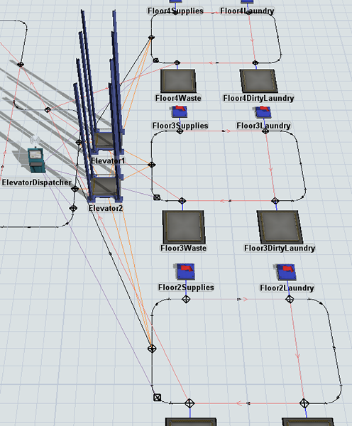
When you're finished, your 3D model will look similar to the following image:
To add elevator redirect and entry control points:
- Add a Control Point to the lower path in the elevator area so that it will be the first control point an AGV passes over when it enters the elevator area.
- Add a Control Point to the floor 2 area so that an AGV will pass over this control point right after leaving the control point connected to the Floor2Waste queue.
- Repeat the previous step to add identical control points to the floor 3 and floor 4 areas as well.
- For clarity, rename the new control points Floor1ElevatorRedirect, Floor2ElevatorRediect, etc.
- Create a connection (A-connect) from the Floor1ElevatorRedirect control point to Elevator1 to open a menu. Select ElevatorRedirectCP. A purple line will appear connecting the control point and the elevator.
- Repeat the previous step to connect the Floor2ElevatorRedirect, Floor3ElevatorRedirect, and Floor4ElevatorRedirect control points to the Elevator1 as well.
- Click the Floor2ElevatorRedirect control point to
select it. In Properties, under the Labels group,
click the Add button
to open a menu. Select
Add Number Label to add a new label.
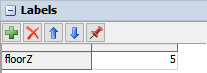
- Name the label
floorZ. - Set the value to
5. - Repeat the previous steps for Floor3ElevatorRedirect
control point to create a floorZ label with a value
10. - Repeat the previous steps for Floor4ElevatorRedirect
control point to create a floorZ label with a value
15. - Repeat the previous steps for Floor1ElevatorRedirect
control point to create a floorZ label with a value
0. - Add a Control Point to the AGV path near Elevator1.
- Add a Control Point to the floor 2 area in the middle of the left path.
- Repeat the previous step to add identical control points to the floor 3 and floor 4 areas as well.
- For clarity, rename the new control points Floor1Entrance, Floor2Entrance, etc.
- Press and hold the A key to enter connection mode. Click the Floor1Entrance control point to select it. Then, click Elevator1 to open a menu. Select ElevatorFloorCP. An orange line will appear connecting the control point and the elevator.
- Repeat the previous step to connect the Floor2Entrance, Floor3Entrance, and Floor4Entrance control points to the elevator as well.
Reset and run the simulation model:
Now as the simulation model runs, the AGVs will use the elevators to move from one floor to another. Notice also that the elevator raises to different Z-heights depending on the floor it is traveling to. The elevator knows which height to move to because of the floorZ label that you set for each elevator redirect control point.
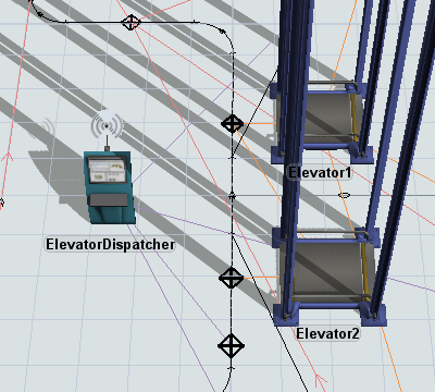
Step 7 Add a Second Elevator
In this step, you'll learn about the changes you would make to an AGV model if you decided to use more than one elevator. You'll add a second elevator and a dispatcher that will control which elevator the AGVs take to get to an upper floor. You'll also change the connections needed to operate with two elevators.
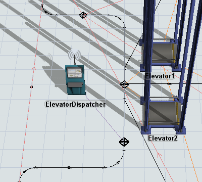
When you're finished, your model will look similar to the following image:
To add a second elevator:
- From the Library, add the following 3D objects to the elevator area of the model:
- An Elevator
- A Dispatcher
- For clarity, rename Dispatcher1 as ElevatorDispatcher.
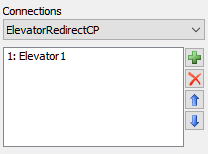
- Click the Floor1ElevatorRedirect control point to select it. In Properties, click the Connections menu. Select ElevatorRedirectCP.
- In the box below this menu, click Elevator1 to select
it. Click the Remove button
 to delete this connection.
 - Repeat the previous steps to remove the elevator redirect connections from Floor2ElevatorRedirect, Floor3ElevatorRedirect, and Floor4ElevatorRedirect as well.
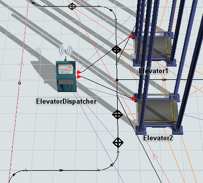
- Press and hold the A key to enter connection mode. Click the Floor1ElevatorRedirect control point. Then, click the ElevatorDispatcher to open a menu. Select ElevatorRedirectCP. A purple line will appear connecting the control point and the dispatcher.
- Repeat the previous step to connect the Floor2ElevatorRedirect, Floor3ElevatorRedirect, and Floor3ElevatorRedirect control points to the ElevatorDispatcher as well.
- Move the Floor1Entrance so that it is directly in front of the Elevator1.
- Rename this control point Floor1Entrance1.
- From the Library, add a Control Point and place it directly in front of Elevator2.
- Rename the new control point Floor1Entrance2.
- Press and hold the A key to enter connection mode. Click the Floor1Entrance1 control point to select it. Then, click Elevator2 to open a menu. Select ElevatorFloorCP. An orange line will appear connecting the control point and the second elevator.
- Repeat the previous step to connect the Floor2Entrance, Floor3Entrance, and Floor4Entrance control points to Elevator2 as well.
- Create input port connections (A-connects) going from the ElevatorDispatcher to both Elevator1 and Elevator2.
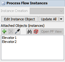
- On the main toolbar, click the Process Flow button to open a menu. Select AGV Elevator to open this process flow.
- Click a blank area in the process flow to ensure nothing is selected.
- In Properties under the Process Flow Instances
find the Attached Objects (instances) box. Click the
Sampler button
to enter sampling mode.
- In the 3D model, click Elevator2 to attach it to the process flow template.
Reset and run the model:
As the model runs, the AGVs will now use both elevators to move from one floor to another.
Conclusion
Now you've learned how to integrate elevators into an AGV model as needed. In the next tutorial, you'll learn about some additional AGV settings that you can use to customize your AGVs. You'll learn how to adjust load times, speeds, and other settings. Continue on to Tutorial 4.4 - Custom AGV Settings.