Task 2.1 - Build a Basic Task Sequence
Task Overview
In this tutorial task, you'll learn how to create a very basic task sequence in a process flow. You'll learn how to link this process flow to a 3D model so that it will control task executers in the model. This tutorial task will also introduce you to the concept of process flow instances.
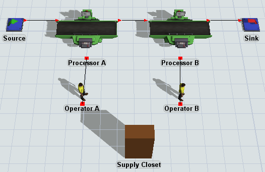
You'll build a simple task sequence for loading and unloading flow items that will be used by two different operators in the 3D model. When you're finished with this task, your 3D model should look like this:
Using Labels to Connect to the 3D Model
In this model, you'll use labels extensively to link tokens in a process flow to objects in the 3D model. Process flows can control the logic of the 3D model using labels that contain a reference to a 3D object in the model. As the token moves through the activities in the process flow, the activity's logic can be applied to the object in the 3D model using this reference. Consider reading Key Concepts About Labels for a deeper understanding of how to work with labels in a process flow.
In this model, you'll use labels to:
- Link tokens to flow items in the 3D model - You'll create a label named item to link tokens in a process flow to the flow items that need to be transported in the 3D model.
- Dynamically set flow item destinations - A label named destination on the flow item will track which processor the flow item should be transported to. The process flow will reference this label in the transportation task sequence.
Step 1 Build the 3D Model
In this step, you'll add the basic objects that will represent your production line in your 3D simulation model. You'll also change the properties of a shape object to make it look like a cleaning supplies closet. Be aware that the closet won't be used until the next task in the tutorial when you create a more advanced task sequence. When you're finished, your model will look like this:
To create this model:
- In a new model, add the following 3D objects from the Library:
- 1 Source
- 2 Processors
- 1 Sink
- 2 Operators
- 1 Shape (found under the Visual group)
- For clarity, rename the 3D objects as follows:
- Create port connections (A-connects) between the following objects:
- From the Source to Processor A
- From Processor A to Processor B
- From Processor B to the Sink
- Create center port connections (S-connects) between the following objects:
- From Processor A to Operator A
- From Processor B to Operator B
- Click the Supply Closet shape to bring up its properties on the right.
- Under the Visual Tool section, open the Visual Display menu and select Cube.
- Under the Visuals section, click the arrow next to the Color box and select the dark brown color.
- Under the Position, Rotation, and Size group, find the
Size
 boxes and type the following numbers:
- X-Size: 1.50
- Y-Size: 0.75
- Z-Size: 3.00
| Object | New Name |
|---|---|
| Source | Source (remove any numerals) |
| Sink | Sink (remove any numerals) |
| First Processor | Processor A |
| Second Processor | Processor B |
| First Operator | Operator A |
| Second Operator | Operator B |
| Shape | Supply Closet |
Check to make sure that your final 3D model looks like the image in the beginning of this step.
Step 2 Build a Task Sequence Sub Flow
Now you'll create a simple task sequence that both operators will use whenever they need to load and unload a flow item. You'll create a sub flow because process flows can easily use sub flows to assign task sequences to task executers.
In this step, you'll set the process flow to run a separate instance each time an operator runs the sub flow. That means that each operator will use the same sub flow to provide them with the basic template for the task sequence. But each operator will run its own instance of the process flow, which is like running its own copy of the process flow. One advantage of this method is that any shared assets used by the operators will be local to the two operators. See Sub Process Flows and Process Flow Instances for more information.
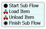
In this step, you'll only add the activities to the process flow. You'll edit the properties and create the logic in a later step. When you're finished, your process flow will look like this:
To build this process flow:
- On the main toolbar, click the Process Flow button to open a menu. Select Add a Sub Flow to open a new process flow.
- In Properties, in the Process Flow Name box,
delete the current text and type
TransportItems. - Under the Process Flow Instances group, open the Instance Creation menu and select Per Instance.
- From the Library, add the following activities to the process flow, arranging them
in a stacked block in this exact order:
- A Start activity (under the Sub Flow group)
- A Load activity (under the Task Sequences group)
- An Unload activity (under the Task Sequences group)
- A Finish activity (under the Sub Flow group)
- For clarity, rename the activities as follows:
| Activity | New Name |
|---|---|
| Start | Start Sub Flow |
| Load | Load Item |
| Unload | Unload Item |
| Finish | Finish Sub Flow |
Check to make sure that your process flow looks similar to the image at the beginning of this step.
Step 3 Attach 3D Objects to the Process Flow
Now you'll link this sub flow to the objects simulation model. On the processor, you'll use a special picklist option called Use Task Sequence Sub Flow that will allow you to dynamically run the task sequence every time the processor uses an operator to transport a flow item. You'll set the picklist options so that the processor will assign the task to the operator connected to its center port.
To attach the 3D objects:
- In the 3D model, click Processor A to bring up its properties on the right.
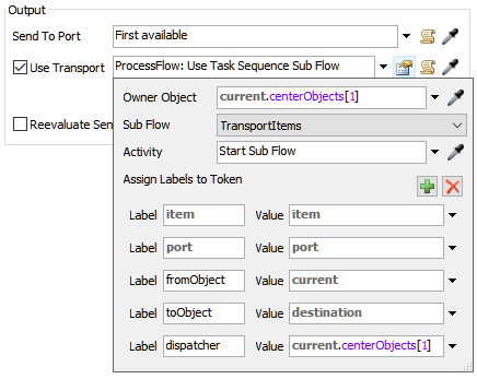
- Under the Output section, check the Use Transport checkbox.
- Click the arrow next to the Use Transport box to open a menu. Select Customized Logic then ProcessFlow: Use Task Sequence Sub Flow from the menu to open the options for this picklist.
- Click the arrow next to the Owner Object to open a menu. Select current.centerObjects[1] from the menu.
- Check to ensure that the selected sub flow in the Sub Flow box is TransportItems, which is the sub flow you created in the previous tutorial step.
- Click the arrow next to the Activity box to open a menu. Select Start.
- You'll use the default labels in the picklist.
- Repeat the previous steps for Processor B.
Consider saving your simulation model.
Step 4 Add Dynamic References to the Sub Flow
The following table provides an overview of how the activities in this process flow will function:
| Activity | Explanation |
|---|---|
| Start Sub Flow | All new tasks generated by the processor will create a token which starts here in the process flow. |
| Load Item | The operator connected to the processor's center port will load the flow item. |
| Unload Item | The operator will take the flow item to the downstream fixed resource connected to the processor's output port. |
| Finish | When the sub flow is complete, the token will enter this activity and be destroyed, indicating the task is now complete. |
In this step, you'll edit the activities in your sub flow so that it is dynamic, meaning it will change based on conditions that are unique to each instance (each processor and operator) that are attached to the sub flow. As a reminder, each time an operator picks up a flow item from the processor and transports it to its destination, that will act as a separate instance of a sub flow.
You'll use the current keyword to refer to whichever object instance is attached to the sub flow. In this case, this will be either Operator A or Operator B, depending on which processor created the task sequence. Using the current keyword allows both operators to run separate copies (instances) of the same task sequence. Running instances is more efficient since you'll only need to build the task sequence once, rather than building one for each operator.
You'll also add references to labels on the token. When the processor calls this task sequence sub flow, it will create a token to represent the task that needs to be completed. Recall that in the previous tutorial step, you set up the labels that would be assigned to this token. The item label contains a dynamic reference to the flow item that needs transportation and the toObject label contains a dynamic reference to the downstream object that will receive the flow item.
To edit these properties on the process flow:
- With the process flow open, click the stacked block to select it.
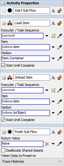
- In Properties, under the Load Item activity, click the arrow next to the Executer / Task Sequence box to open a menu. Select current (Instance Object).
- Repeat this step for the Unload Item activity as well.
- Confirm that both the Load Item and
Unload Item activity have
token.itemlisted in the Item box. - In the Unload Item activity, in the
Station box, delete the existing text and type
token.toObject.
When you're finished, the Properties should look similar to this image:
Step 5 View Instances During a Simulation Run
In this step, you'll learn how to open up process flow instances so that you can view them during a simulation run:
- Reset and run the simulation model. Let the simulation run long enough for both operators to begin working on the loading task sequences.
- Click a blank space in the process flow to ensure nothing is selected.
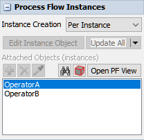
- In Properties, under the Process Flow Instances group, notice that the two operators should appear in the Attached Objects (instances) list. Click Operator A in the list to select it.
- Click the Open PF View button. A new tab in the process flow will open to show the process flow instance for Operator A.
- Return to the original process flow and repeat the previous steps to open the process flow instance for Operator B as well.
- If desired, you can split the pane so that you can see all three process flows at the same time. See Arranging Windows and Tabs for more information.
- If you paused the simulation model, resume running the model now.
As the simulation runs, you'll see the operators loading and unloading flow items in the 3D model. In the TransportItems process flow, you'll see one or two tokens moving through the process flow each time an operator loads and unloads a flow item. Notice also that each of the two process flow instances of the operators correlate with the operators in the 3D model and with the TransportItems process flow.
Conclusion
At this stage, your process flow is very basic and doesn't operate much differently than the standard pre-programmed logic that is available with the Use Transport property on fixed resource. However, in the next tutorial task, you'll see how a process flow allows you to add additional custom tasks that make it much easier to assign complex task sequences to task executers. Continue on to Tutorial Task 2.2 - Customize the Task Sequence.